97
Operation
F-FEM-CON — User’s Guide
4.12.14
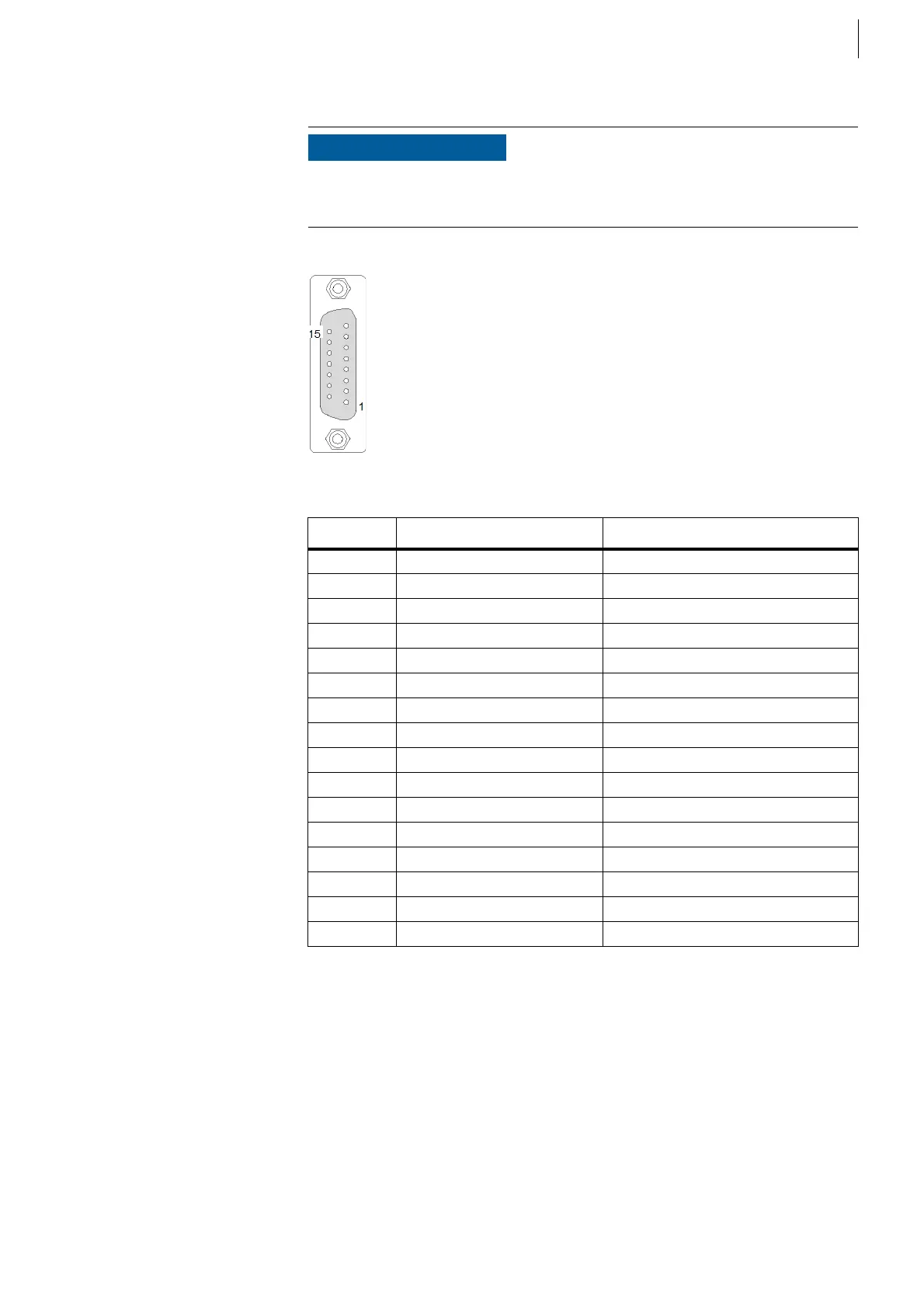
Debug/JTAG Connection: X27
This connector is assembled on the rear side of the F-FEM-CON Advanced.
NOTICE
This connector may only be used for the production test.
No cable may be connected during regular operation.
Fig. 71
Pin Signal at X27 Description
1DGND Ground
2 FLASH Ry/By
3 FLASH WEn
4 VDD out (3.3V) max. 50 mA
5DGND
6nc
7DGND
8 WDDIS Watchdog disabled
9EMUn Emulation
10 nc
11 TMS Test Mode Select
12 TCK Test Clock
13 TRSTn Test Reset
14 TDI Data in
15 TDO Data out
Case Shielding Shielding
Tab. 34
 Loading...

