General
16
F-FEM-CON — User’s Guide
2.2 System Environment
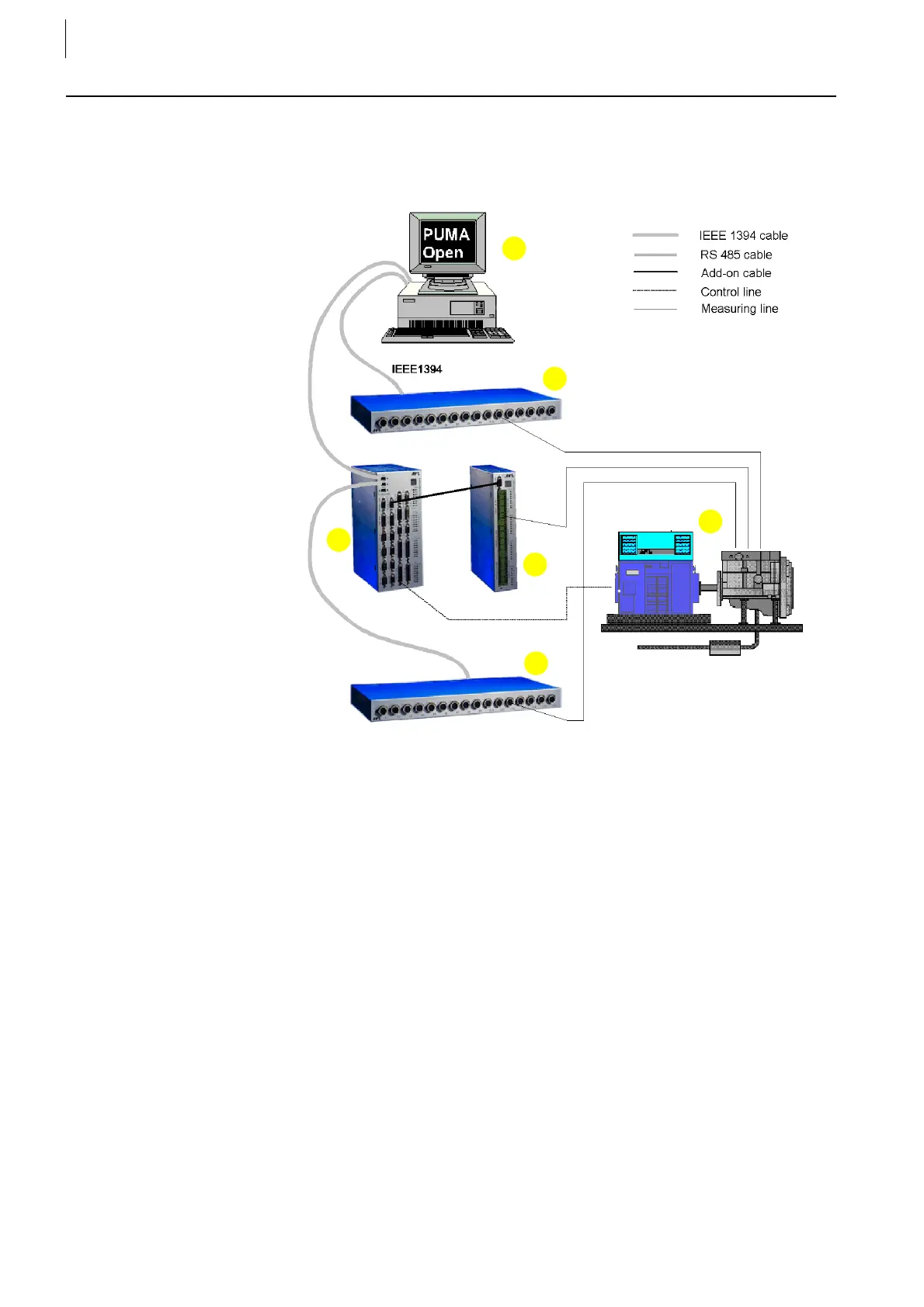
The figure below outlines schematically how F-FEM-CON modules are inte-
grated with the PUMA Open test bed system.
Fig. 2
1..... Test bed workstation (on which the PUMA Open system has been
installed)
2..... F-FEM-AIF, directly connected to the PUMA Open system
3.....Engine test bed (engine, dyno)
4..... F-FEM-AIN or F-FEM-AIS (electrically isolated), connected to the PUMA
Open system via F-FEM-CON
5..... F-FEM-DIO, connected to the PUMA Open system via F-FEM-CON
6..... F-FEM-CON, directly connected to the PUMA Open system
 Loading...

