47
Operation
F-FEM-CON — User’s Guide
4.3 Analog Outputs
Each analog channel is an electrically isolated unit provided with a serial 16 bit
DAC, a precision voltage reference and a voltage and current output stage. To
achieve the desired accuracies, each output is checked during production
testing and the deviations found are stored in the EEPROM of the F-FEM-CON.
The F-FEM-CON software takes these deviations into account and corrects
them (calibration). To achieve optimum accuracy, do not use the voltage output
and the current output of a channel simultaneously.
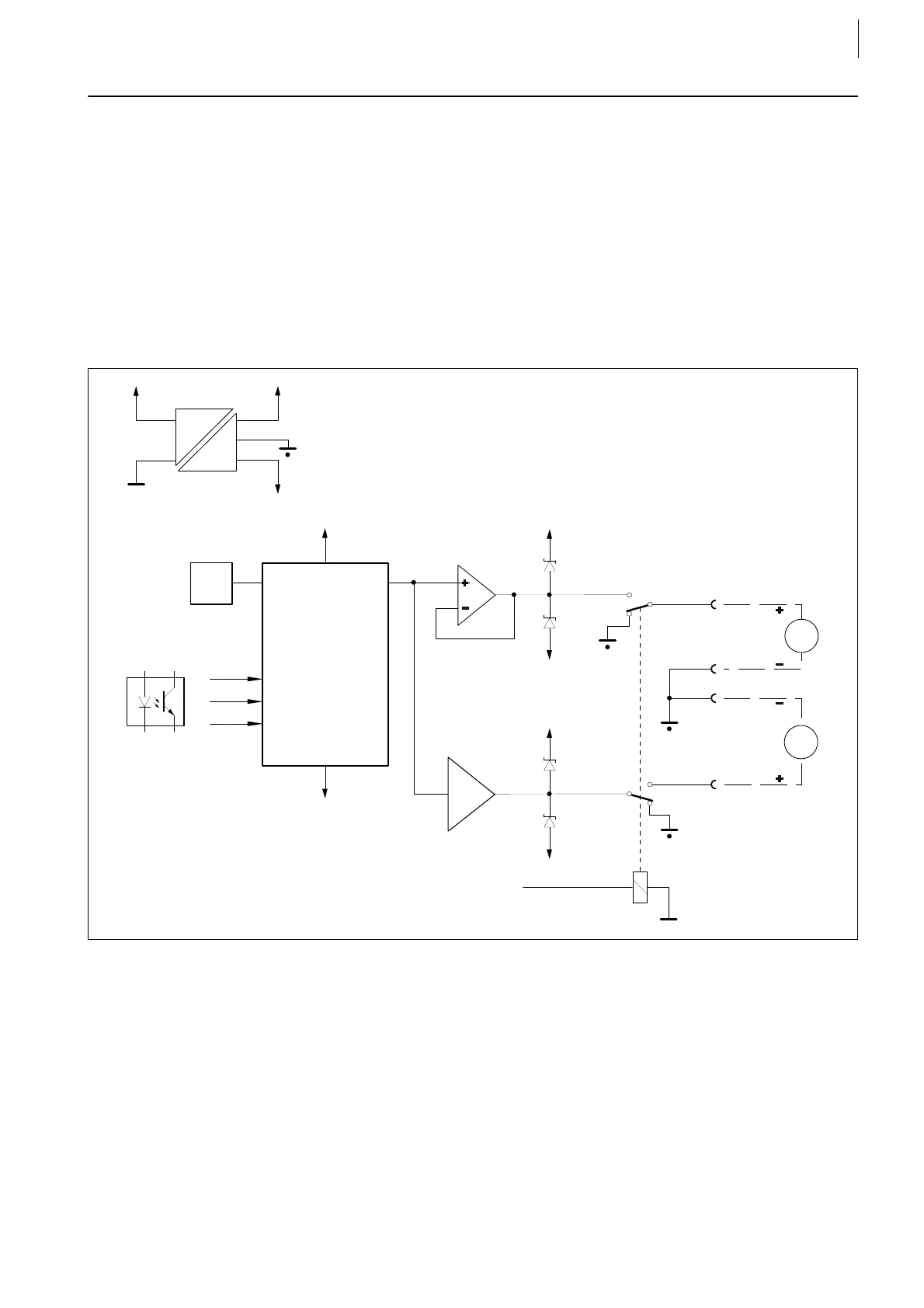
4.3.1
Block Diagram
Circuit of a DAC channel
The pin assignment above applies to X5, X6, X7 and X8.
Fig. 26
from internal logik
5 V
+15 V
-15 V
Data
CLK
LDAC
DAC
+15 V
Ref.
-15 V
+15 V
-15 V
X5/3
+15 V
-15 V
X5/2
X5/4
X5/1
U/I
Converter
Analog Outputs
V
mA
 Loading...

