EasyManuals Logo

AVL F-FEM-CON User Manual

Default Icon
110 pages
To Next Page IconTo Next Page
To Previous Page IconTo Previous Page
Page #71 background imageLoading...
Page #71 background image
71
Operation
F-FEM-CON — Users Guide
"PWM" and "PWM inverted" interpret the duty cycle (DC) in a different way:
F-Out PWM block diagram:
4.7.2.2
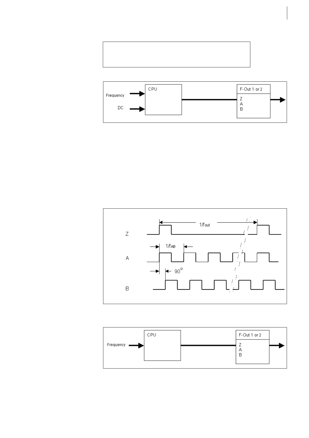
Signal type: Simulate ABZ
The desired frequency is output at the zero track. Tracks A and B, which are in
quadrature, output the desired frequency multiplied by the number of teeth.
The WD-Live signal is output at the single channel.
Simulate ABZ block diagram:
DC = ON Time / Time Period * 100%
respectively
DC inverted = OFF Time / Time Period * 100%
Fig. 45
Fig. 46
Fig. 47
f
AB
=
f
out
·
Z
N

Table of Contents

Questions and Answers:

Question and Answer IconNeed help?

Do you have a question about the AVL F-FEM-CON and is the answer not in the manual?

AVL F-FEM-CON Specifications

General IconGeneral
BrandAVL
ModelF-FEM-CON
CategoryMeasuring Instruments
LanguageEnglish

Related product manuals