Operation
86
F-FEM-CON — User’s Guide
4.12.2
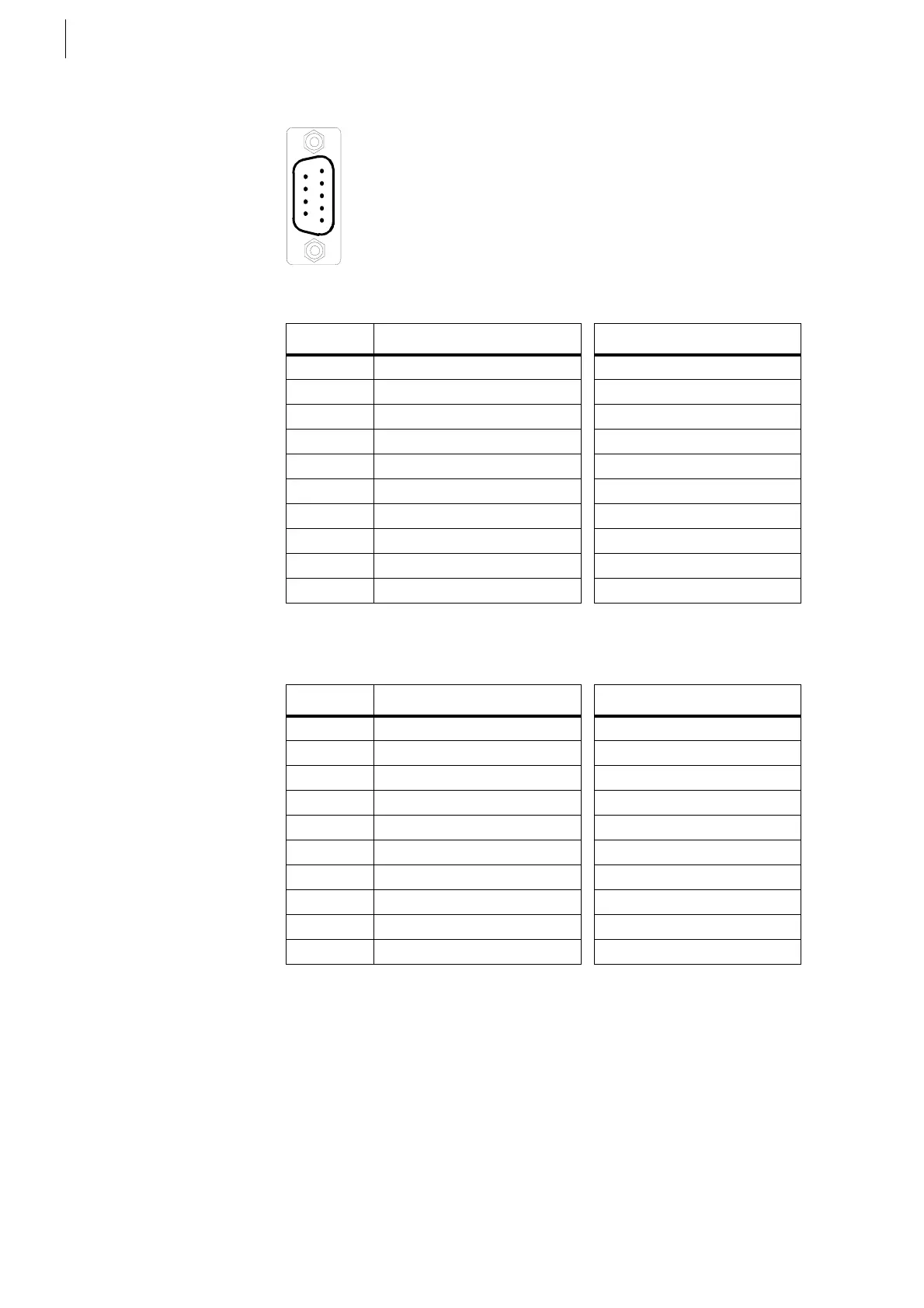
Analog Inputs X1 ... X4
*) Only for F-FEM-CON Advanced
*) Only for F-FEM-CON Advanced:
Pins 8 is connected to 24 V (max. 0.3 A). This ensures a sensor supply via the
same cable as used, for example, for pressure transmitters with 4 ...20 mA
2-wire, 0 ...20 mA 4-wire or 0 ...10 V 4-wire. Suggestions for wiring can be found
in the operating manual for the F-FEM-AIF.
By bridging Pin 5 and Pin 9, the electrical isolation is removed and the analog
ground of the relevant channel is connected to the digital ground.
Fig. 59
Pin Signal at X1 Signal at X2
1 U/I in1– U/I in2–
2 U/I in1+ U/I in2+
3
4 AIGND_1 AIGND_2
5 AIGND_1 (opt.) AIGND_2 (opt.)
6 GND_24 GND_24
7
8 NC (+ 24 V *) NC (+ 24 V *)
9DGND DGND
Case Shielding Shielding
Tab. 20
Pin Signal at X3 Signal at X4
1 U/I in3– U/I in4–
2 U/I in3+ U/I in4+
3
4 AIGND_3 AIGND_4
5 AIGND_3 (opt.) AIGND_4 (opt.)
6 GND_24 GND_24
7
8 NC (+ 24 V *) NC (+ 24 V *)
9DGND DGND
Case Shielding Shielding
Tab. 21
 Loading...

