73
Operation
F-FEM-CON — User’s Guide
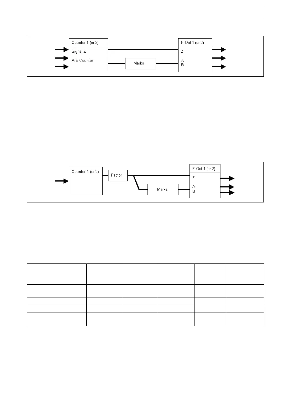
Block diagram SiSp Counter n Direct Z:
SiSp Counter 1 and/or SiSp Counter 2
The frequencies that are measured at the counter channels 1 and 2 are
output again at F-OUT 1 and F-OUT 2. A factor for multiplication (or divi-
sion) can be applied.
Tracks A and B are determined by the counter frequency * factor divided by
the number of marks.
The relation to the original dead center will be lost in this case. Cross-
bonding of the channels 1 and 2 or doubling of the tracks 1 and 2 is pos-
sible! All 3 tracks (A, B, Z ) are phase locked at the output. This function is
also called "Full Split".
Block diagram SiSp Counter n:
All definable options are described in the "F-FEM Parameterization" manual. An
overview is given below:
Fig. 50
Fig. 51
yes: possible, is maintained
no: not possible, is not maintained
– no meaning
Signal type Crossbonding TDC relation
to source
Phase relation
A/B to Z
Selectable
marks
Factor (multi-
plication/divi-
sion)
Simulate ABZ – – yes yes 16 values in
calibration table
SiSp Counter n DABZ yes yes yes no no
SiSp Counter n DZ no yes no yes no
SiSp Counter n (Full Split) yes no yes yes first value in
calibration table
Tab. 14
 Loading...

