DESCRIPTION AND OPERATION
STATUS SIGNALS
I-E96-506B1 2 - 5
STATUS SIGNALS
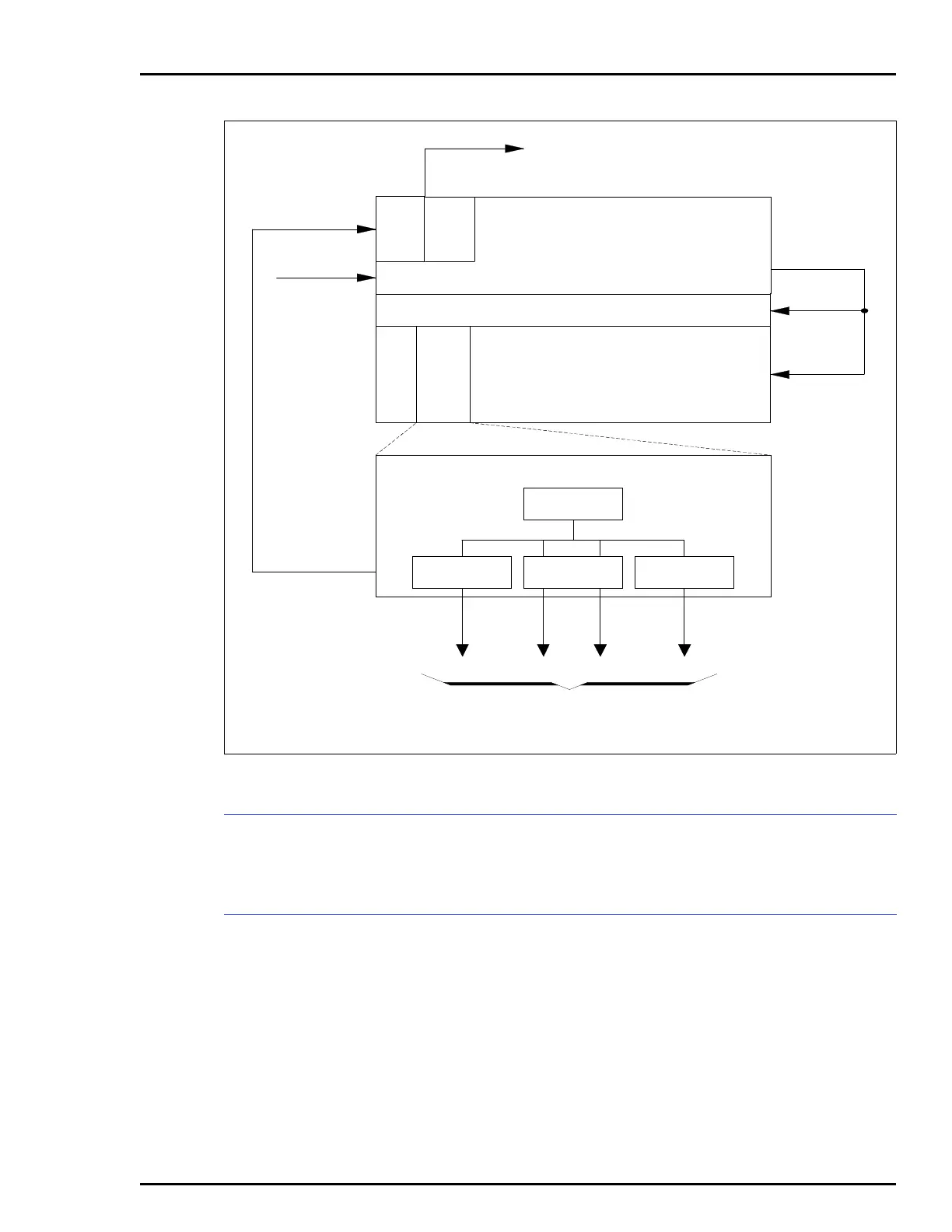
The block diagram in Figure 2-4 shows the flow of status sig-
nals through the system.
Power System Status
All status lines, AC line, bus voltages, external power inputs,
external customer status inputs, and power module status are
ANDed in the bus monitor module. Bus monitor circuitry
determines if any status line is bad. If any status is bad, the
bus monitor module generates a low-true output signal to the
communication system hardware, which is the bus interface
module for Plant Loop systems, and the network interface
module for INFI-NET systems.
Figure 2-2. Power Distribution to the IEPAS02 System Power Module
BMM
POWER ENTRY PANEL
MODULE MOUNTING UNIT
OR
POWER MOUNTING UNIT
POWER SUPPLY MODULE
DC
CONV
DC
CONV
DC
CONV
±15 VDC
ALARMS
TP50305B
+24 VDC
+5 VDC
AC OUT
AC IN
AC/DC
CONV
TO PROCESS
CONTROL
MODULES
STATUS OUT
PAS
FAN ASSEMBLY
ATM
Artisan Technology Group - Quality Instrumentation ... Guaranteed | (888) 88-SOURCE | www.artisantg.com