DESCRIPTION AND OPERATION
STATUS SIGNALS
I-E96-506B1 2 - 7
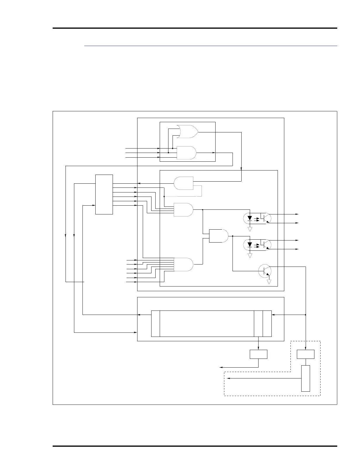
Customer Alarm Outputs
There are two customer alarm outputs (normally closed): bus
voltage and power system status alarm. The bus voltage alarm
activates (opens) if any bus voltage goes low or is lost. The
power system status alarm activates (opens) for any bad sta-
tus. These outputs are optically isolated and can drive relays
or annunciator panels.
Figure 2-4. Status Signal Block Diagram
AC LINE 1
AC LINE 2
MODULE STATUS
PFI
+5 V
+15 V
–15 V
+24 V
PM STAT
DC BUS
STATUS
PFI
ATM
IEPEP03
BMM
AUX BUS MONITOR 1
AUX BUS MONITOR 2
STATUS IN 1
STATUS IN 2
MODULE STATUS (BMM)
MODULE STATUS (ATM)
PM STAT
IEPAS02
IEPAF02 IEMMU01/02
LIM BIM
POWER
SYSTEM
STATUS
NIS
PFI
TU TU
TP50304B
PLANT LOOP
MCS, OIS,
ETC.
INFI-NET
BUS
VOLT
ALARM
POWER
SYS
ALARM
+
+
–
–
Artisan Technology Group - Quality Instrumentation ... Guaranteed | (888) 88-SOURCE | www.artisantg.com