INSTALLATION
IEPMU01 AND IEPMU02 POWER MOUNTING UNIT INSTALLATION
3 - 16 I-E96-506B1
®
10. Attach one spade lug end of 10 AWG wire assembly to the
PMU +15 VDC. Attach the other spade lug end to system power
bus bar +15 VDC.
11. Attach one spade lug end of a 10 AWG wire assembly to
PMU -15 VDC. Attach the other spade lug end to system power
bus bar -15 VDC.
12. Attach the spade lug end of cable 6637813_1 (IEPEP03
panel only) to STATUS on the PMU card cage (see Figure C-2).
13. Make the other signal connections from J2 to the system
power bus bar using cable 6637813_1.
14. Use an ohmmeter to verify continuity between TB2 on the
IEPEP03 and the AC terminals on the power mounting unit.
15. Verify the circuit breakers on the PEP panel are in the off
position. If you are wiring an IEPEP01 panel, verify that the
external circuit breakers are in the off position.
16. Unplug all process and I/O modules from the MMU back-
plane.
17. Verify that all wiring connections are complete before turn-
ing the source power on.
18. Turn source power on.
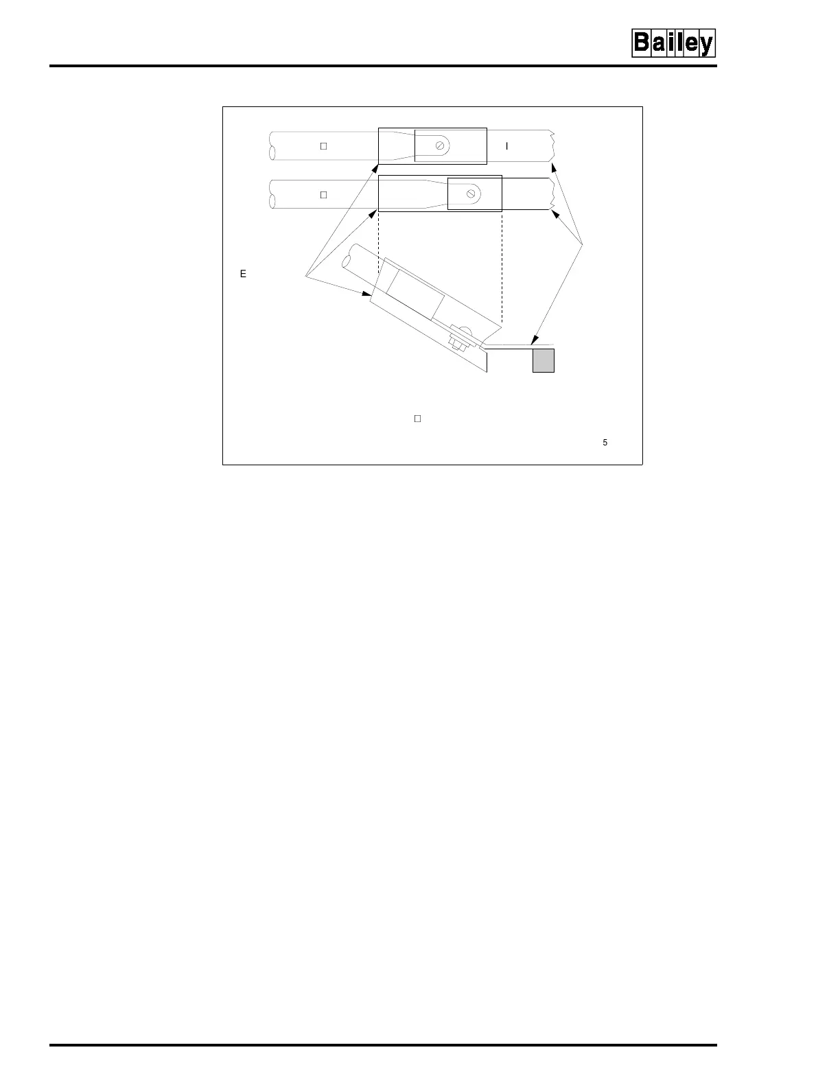
Figure 3-9. Heat Shrink Tubing for 24 VDC Connection
6632285 48
I/O COM
6632285 48
HEAT SHRINK
TUBING
PMU
BUS BAR
STANDOFF
+24 V
NOTE: AFTER JUMPER CONNECTION IS MADE, SLIDE HEAT SHRINK
TUBING SUPPLIED WITH P/N 6632285 48 OVER CONNECTION
UNTIL CONNECTION IS COVERED COMPLETELY AND SHRINK INTO
PLACE WITH HEAT GUN.
TP50375B
Artisan Technology Group - Quality Instrumentation ... Guaranteed | (888) 88-SOURCE | www.artisantg.com