INSTALLATION
IEPEP03 POWER ENTRY PANEL WIRING
I-E96-506B1 3 - 3
2. Connect the primary 120 VAC or 240 VAC power lines to
TB1-1, TB1-2 and TB1-3.
3. Connect the secondary AC power lines (if used) to TB1-4,
TB1-5 and TB1-6. Both inputs must be the same nominal volt-
age level.
If only one AC power input is being used, proceed with Step 4.
If not, skip to Step 5.
4. Connect TB1-1 to TB1-4, TB1-2 to TB1-5, and TB1-3 to
TB1-6. Use 12 AWG as a minimum and 6 AWG as a maximum.
Note that this step avoids false bad status information because
it connects line 1 and line 2 inputs together.
5. Connect cable 6637813_1 from J2 on the power entry
panel to the system power bus bar. This cable provides connec-
tions to sample the DC bus voltages, monitor the power
module status signal and output a power fail interrupt signal.
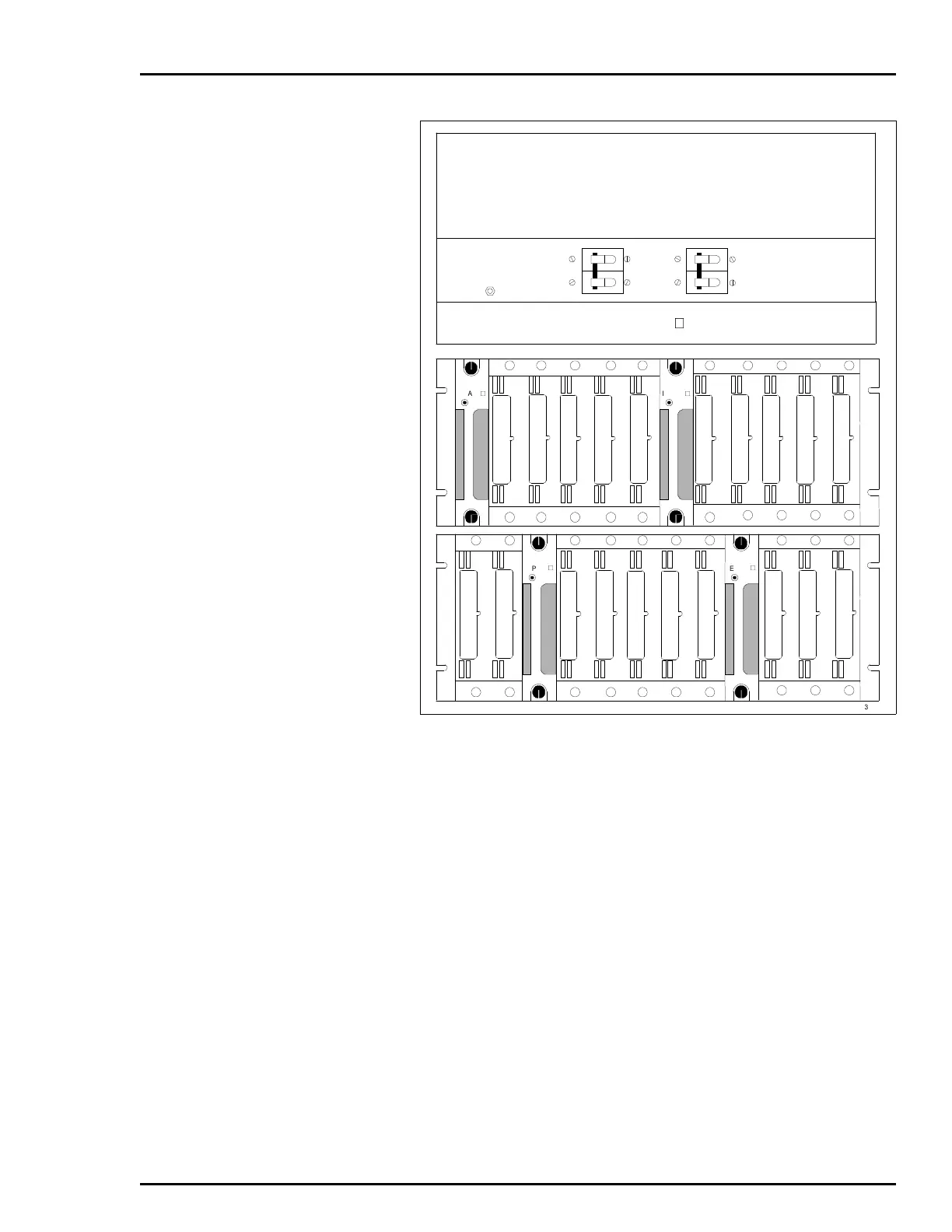
Figure 3-1. Circuit Breakers CB1/CB2
IEPEP03
WRIST
STRAP
GROUND
CB2 CB1LINE 2 LINE 1
IEFAN0
IEPAS0
IEPAS0
IEPAS0
IEPAS0
TP25377B
Artisan Technology Group - Quality Instrumentation ... Guaranteed | (888) 88-SOURCE | www.artisantg.com