INSTALLATION
IEPEP03 POWER ENTRY PANEL WIRING
3 - 10 I-E96-506B1
®
To install the power supply module:
1. Set jumpers J1 through J3 on the IEPAS02 module and set
jumpers J1 and J2 on the IEPAF02 module (the IEPAF02 mod-
ule does not have J3) for the module operation desired. Table
3-3 lists the IEPAS02 and IEPAF02 jumper settings. Figure 3-6
shows the jumper locations on the IEPAS02 and IEPAF02
power modules. Refer to Table 4-2 for information on the mon-
itoring priority levels of the power module jumper settings.
2. Grasp the module faceplate handle and align the top and
bottom edges of the circuit board with the guides in the mod-
ule mounting unit.
3. Hold the module by the faceplate handle and slide it into
the MMU slot. Push on the faceplate until the rear edge con-
nectors of the power module are firmly seated in the backplane
connectors.
4. Firmly press the module handle as you use a blade screw-
driver to push and turn the 2 concentric screws 1/2-turn
clockwise to lock the module in place.
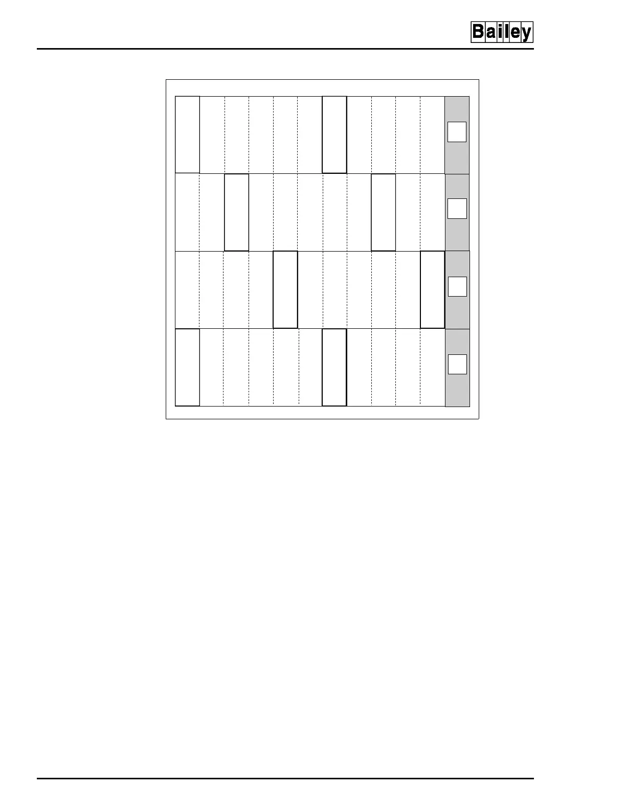
Figure 3-5. Recommended Power Module Layout for Module
Mounting Unit
TP50300A
PAS PAS
1
2
3
4
56
7
89
10 11
12
PASPAS
PAS PAS
PASPAS
NOT
USED
NOT
USED
NOT
USED
NOT
USED
Artisan Technology Group - Quality Instrumentation ... Guaranteed | (888) 88-SOURCE | www.artisantg.com