OPERATING PROCEDURES
LED INDICATORS
4 - 2 I-E96-506B1
®
Power Module
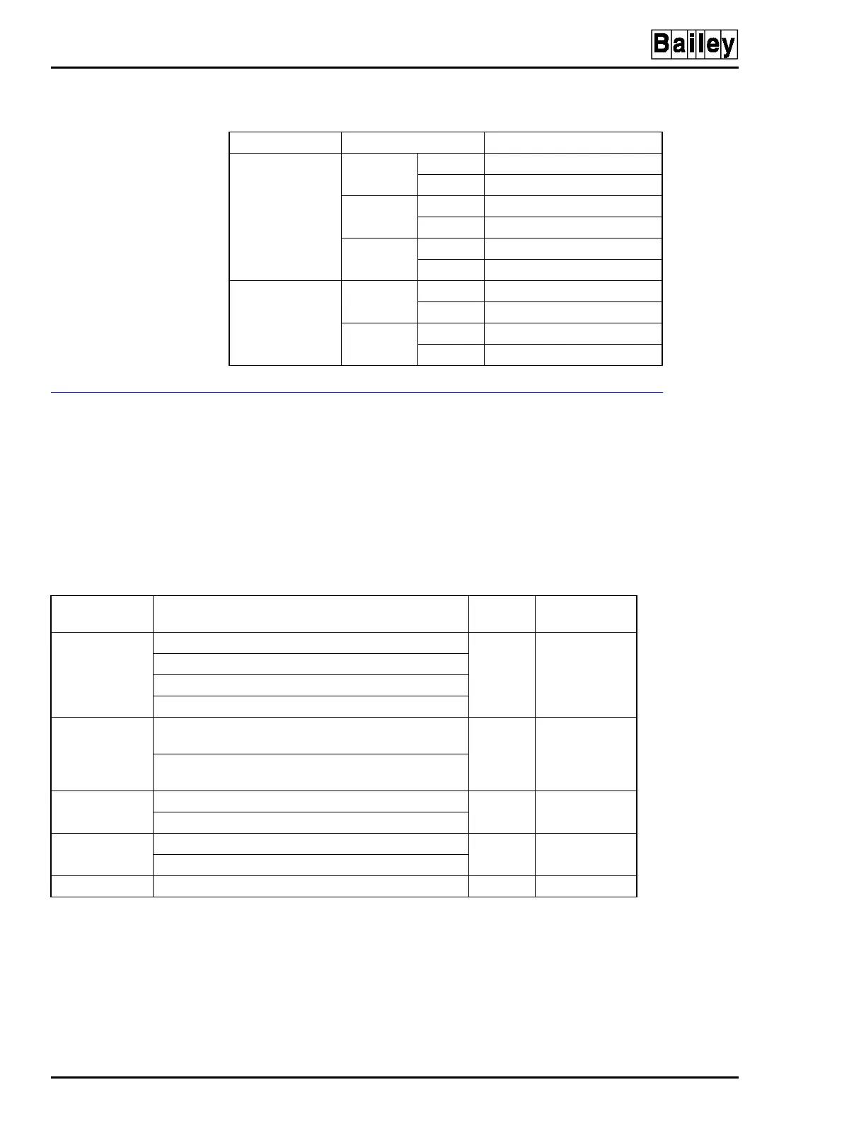
The power module has one LED, module status. This LED is
green when the module is operating normally. This LED has
five possible states that describe the status of the power mod-
ule. Refer to Table 4-2 for a list of power supply faults, the LED
states, priority level and associated power module status
signal.
Table 4-1. Status LEDs, AC Transfer and Bus Monitor Modules
Module LED/Condition Condition
AC transfer
module
Status Green Normal
Red Module has failed
Line 1 Green Line 1 input is good
Red Line 1 input has failed
Line 2 Green Line 2 input is good
Red Line 2 input has failed
Bus monitor
module
Status Green Normal
Red Module has failed
System
Status
Green Normal
Red Bad power system status
Table 4-2. Status LEDs, Priority Level and Status Signal
for IEPAS02 and IEPAF02 Power Modules
LED
State
Fault
Priority
Level
1
Power Module
Status Signal
Red 5 V DC/DC converter failure 1 Low
24 V DC/DC converter failure
+15 V DC/DC converter failure
-15 V DC/DC converter failure
Alternating red
and green
2
5 V DC/DC converter over-temperature
[85°C (192°F)]
2Low
24 V DC/DC converter over-temperature
[85°C (192°F)]
Blinking green 5 V DC/DC converter overcurrent (13 A typical) 3 Low
24 V DC/DC converter overcurrent (4 A typical)
Blinking red
3
5 V DC/DC converter undercurrent (<0.5 A typical) 4 Low
24 V DC/DC converter undercurrent (<0.3 A typical)
Green No faults 5 High
NOTES:
1. Faults with the highest priority will override faults with a lower priority. A 1 represents the highest priority and a 5 represents the
lowest priority.
2. If the 5 V or 24 V DC/DC converter temperature reaches 90°C (203°F) it will shut down and the status LED will show a failure (red).
3. A converter undercurrent condition (blinking red LED) indicates that the power module is not supplying current to the system. It may
be desirable to disable the status LED for converter undercurrent when certain conditions exist such as a small or no 24 VDC load.
Disable the undercurrent status LED by referring to Table 3-3 for the power module jumper settings.
Artisan Technology Group - Quality Instrumentation ... Guaranteed | (888) 88-SOURCE | www.artisantg.com