DESCRIPTION AND OPERATION
STATUS SIGNALS
2 - 6 I-E96-506B1
®
Bus Voltage Status
The system power bus voltages are ANDed together in the BMM
module and output to an isolated customer alarm output (refer
to Table 1-4 for customer alarm output specifications). If any
bus voltage signal falls out of specification, the BMM module
generates a bus voltage alarm.
Power Module Status
The power modules generate their own status signals. These
signals travel on the system power bus bar to the bus monitor
module. The bus monitor module then ANDs this signal with
the other status signals. If it or any other signal is bad, the
BMM module generates a power system status alarm.
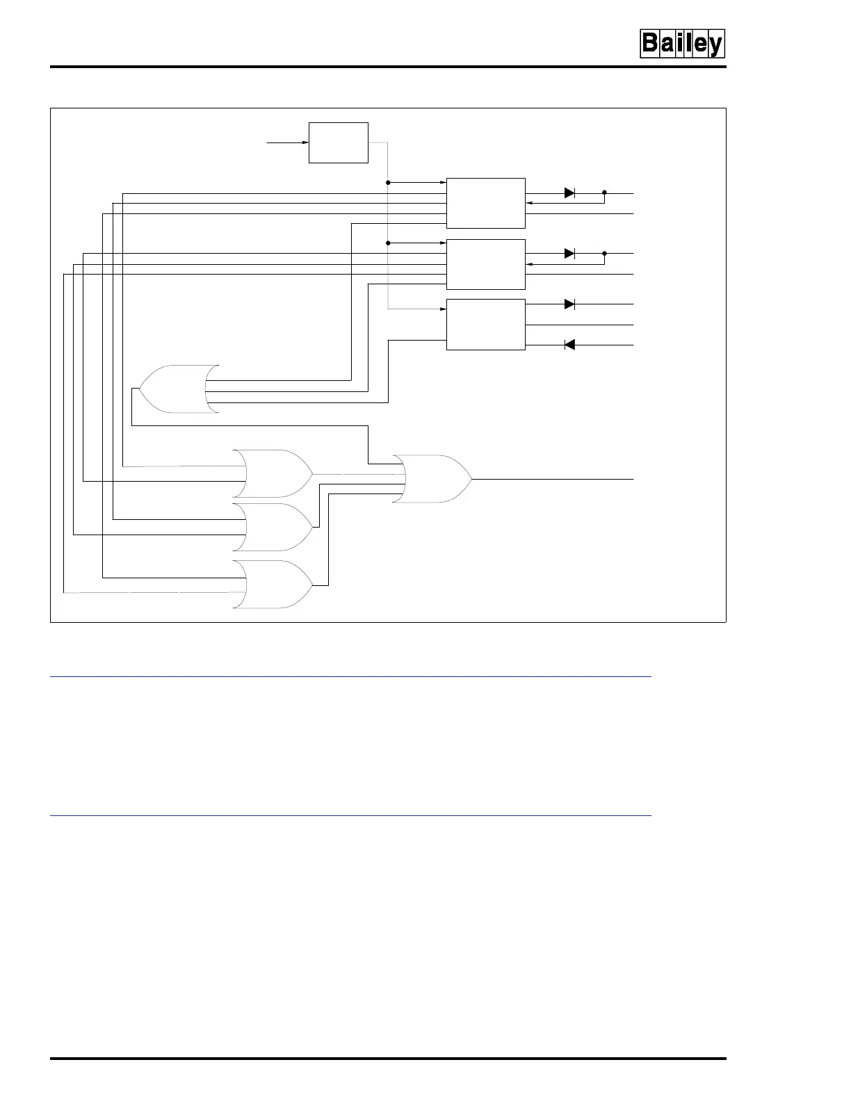
Figure 2-3. IEPAS02 Module Converter and Status Circuitry
24 VDC/DC CONVERTER STATUS
AC AC/DC
DC/DC
I/O POWER 24 V
I/O COMMON
SYSTEM
COMMON
SYSTEM
COMMON
STATUS
ALARM
TP50311B
+5 V
+15 V
–15 V
DC/DC
DC/DC
24 VDC OVERTEMPERATURE
5 VDC UNDERCURRENT
DETECTION
24 VDC UNDERCURRENT
DETECTION
+15/-15 V UNDER/OVERVOLTAGE
5 VDC/DC CONVERTER STATUS
24 VDC OVERLOAD
5 VDC OVERLOAD
5 VDC OVERTEMPERATURE
Artisan Technology Group - Quality Instrumentation ... Guaranteed | (888) 88-SOURCE | www.artisantg.com