INSTALLATION
IEPEP03 POWER ENTRY PANEL WIRING
I-E96-506B1 3 - 7
4. Turn the 2 locking screws on the AC transfer module face-
plate 1/2-turn to lock the module in place.
Bus Monitor Module
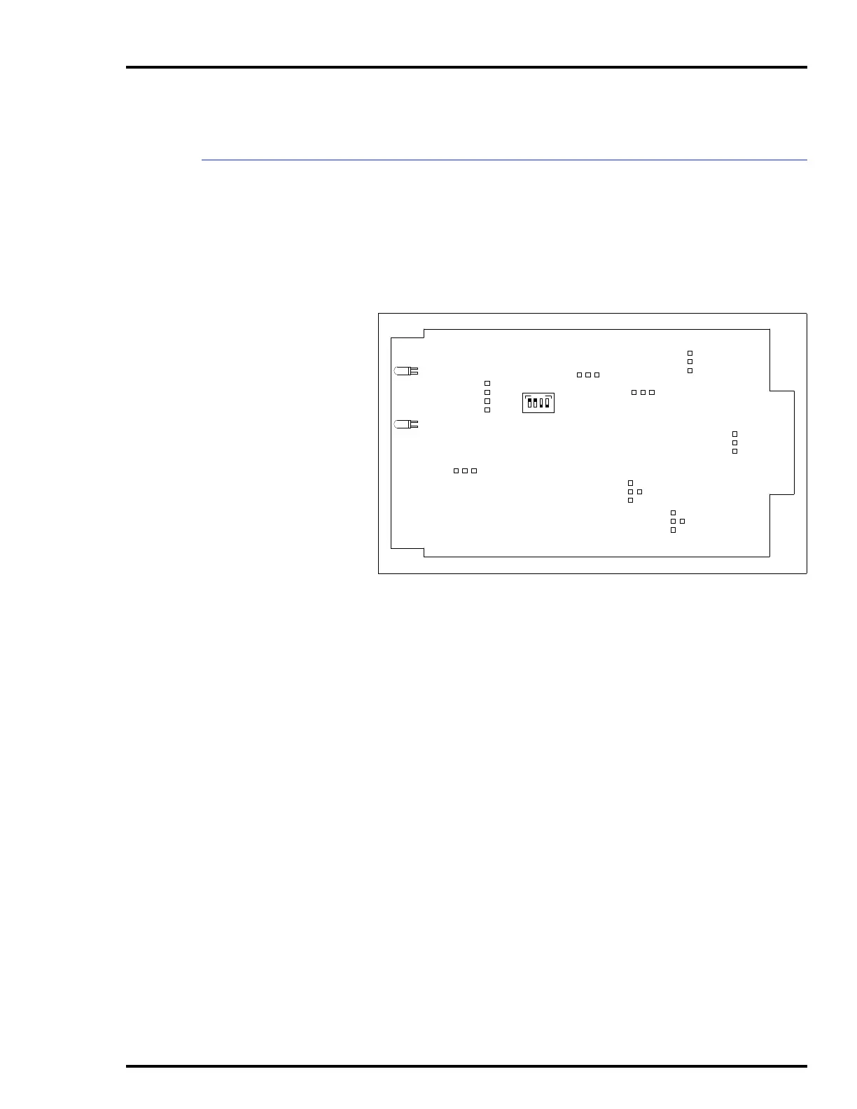
Before mounting the bus monitor module (IEPEP03 Power
Entry Panel only), set switch S1 and jumpers J1 through J8.
Figure 3-4 shows the switch and jumper locations on the bus
monitor module circuit board. Refer to Table 3-1 for the bus
monitor module switch settings. Refer to Table 3-2 for the bus
monitor module jumper settings.
The bus monitor module mounts from the rear of the system
cabinet (see Figure 3-3). The bus monitor module mounts in
the right-most slot. This board has a keyed edge connector to
prevent incorrect mounting.
To mount the module:
1. Grasp the sides of the faceplate.
2. Line up circuit board edges with card guides in the power
entry panel opening.
3. Slide the module in until it locks in place.
4. Turn the 2 locking screws on the bus monitor module face-
plate 1/2-turn to lock the module in place.
Figure 3-4. Bus Monitor Module, Switch S1 and Jumpers J1
through J8
S1
J1
P3
TP50301B
CR12
CR17
ON
1234
J2
J3
J4
J5
J6
J7
1
2
3
4
1
2
3
4
1
2
3
J8
1
2
3
1
2
3
1
2
3
1
2
3
4
1
2
3
Artisan Technology Group - Quality Instrumentation ... Guaranteed | (888) 88-SOURCE | www.artisantg.com