INSTALLATION
IEPMU01 AND IEPMU02 POWER MOUNTING UNIT INSTALLATION
I-E96-506B1 3 - 15
4. Slide heat shrink tubing over the PMU card cage connec-
tion (see Figure 3-8). After properly covering the connections,
use the heat gun to shrink the tubing into place.
5. On the left side of the PMU card cage at the fourth conduc-
tive strip (from the top), attach one end of the second heavy
0 AWG wire assembly (part number 6632285_45).
6. Attach the other end to the system +5 VDC tab at the top of
the system power bus bar.
7. Slide heat shrink tubing over the power mounting unit con-
nection (see Figure 3-8). After properly covering the connec-
tions, use the heat gun to shrink the tubing into place.
8. Attach one end of the 10 AWG wire assembly to the system
power bus bar I/O COM. Attach the other end to the PMU I/O
COM pick-up faston (see Figure 3-9).
NOTE:
For Steps 8 and 11, if more than 15 A are required, use
another system power bus bar connection and attach it to the PMU
I/O terminals, or if desired, stack the ends going to the power mount-
ing unit on a 6 AWG ring lug and connect to the heavy terminal.
9. Attach one end of 10 AWG wire assembly to the system
power bus bar +24 VDC. Attach the other end of 10 AWG wire
assembly to the PMU +24 VDC.
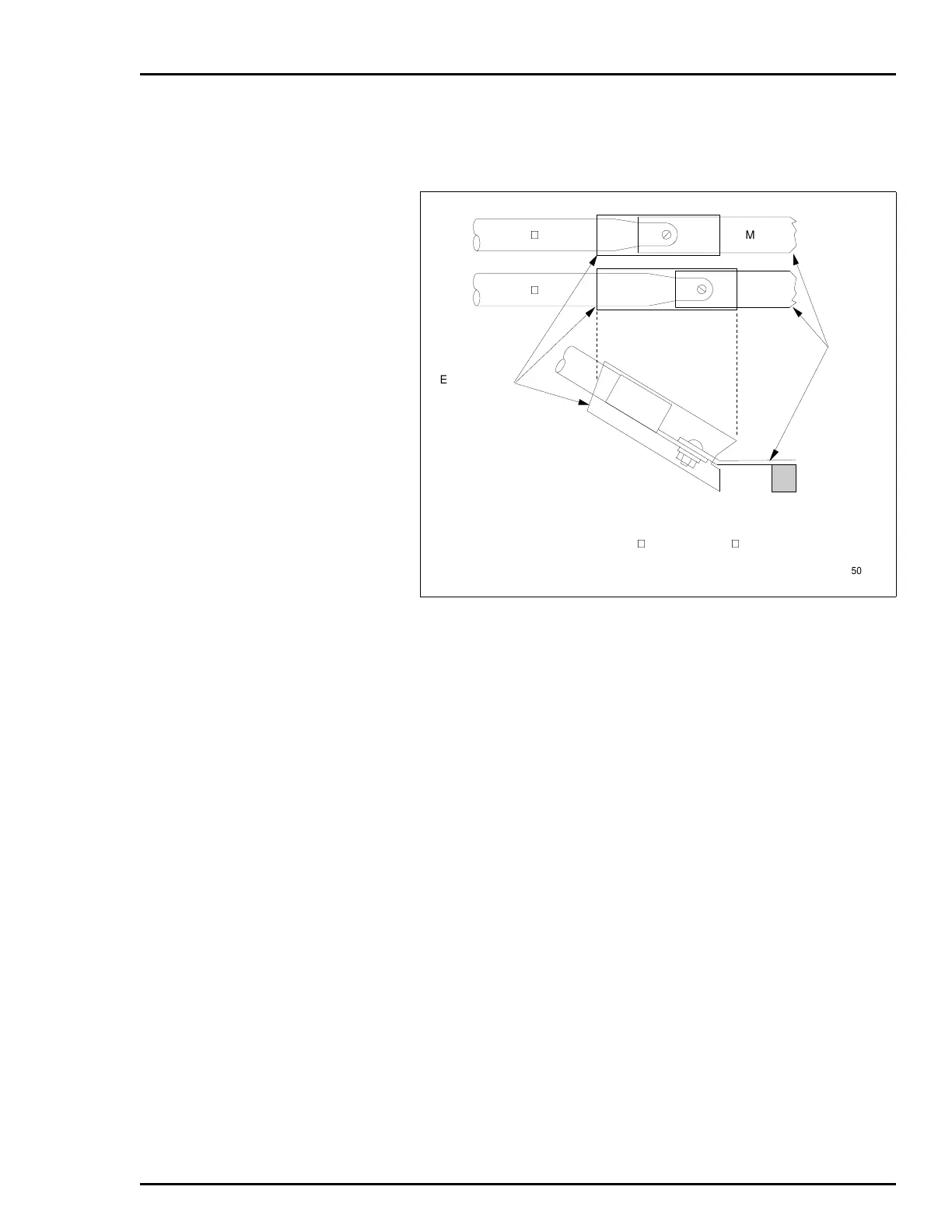
Figure 3-8. Heat Shrink Tubing for 5 VDC Connection
6632285 47
MCOM
6632285 45
HEAT SHRINK
TUBING
PMU
BUS BAR
STANDOFF
+5 V
NOTE: AFTER JUMPER CONNECTION IS MADE, SLIDE HEAT SHRINK
TUBING SUPPLIED WITH P/N 6632285 45 AND 6632285 47 OVER
CONNECTION UNTIL CONNECTION IS COVERED COMPLETELY AND
SHRINK INTO PLACE WITH HEAT GUN.
TP50376B
Artisan Technology Group - Quality Instrumentation ... Guaranteed | (888) 88-SOURCE | www.artisantg.com