INSTALLATION
IEPEP03 POWER ENTRY PANEL WIRING
I-E96-506B1 3 - 5
b. Attach the one wire to TB1-8 on the primary NTCL01
termination unit; the second wire attaches to TB1-8 on the
secondary termination unit.
15. If redundant network interface I/O modules are being used
with the NICL01 termination module:
a. Put two 18 AWG wires on a lug. Attach the lug to TB3-4
(STATUS OUT) on the power entry panel.
b. Attach the primary wire to TB2-4 on the primary
NICL01 termination module; the second wire attaches to
TB2-4 on the secondary termination module.
16. Use TB3-5, TB3-6, TB3-7 and TB3-8 for connecting the
alarms. Use 18 AWG wire. Terminals 5 ( +) and 6 (-) are labeled
PWR SYS. These are the output connections for the power sys-
tem alarm. Terminals 7 (+) and 8 (-) labeled BUS VOLT are the
bus voltage alarm annunciators.
NOTE:
Wire your system per the color codes of the wiring diagrams
in Appendix C.
AC Transfer Module
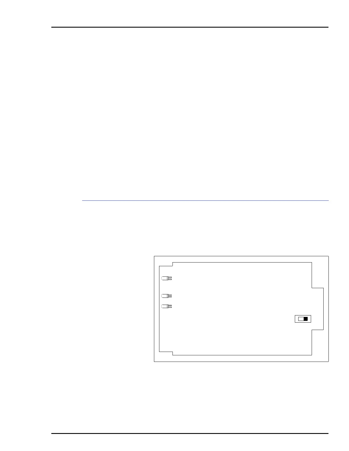
Before installing the AC transfer module (IEPEP03 Power Entry
Panel only), set switch S1 to the rear for 120 VAC operation
(silk-screened 110 on board), or to the front for 240 VAC opera-
tion (silk-screened 220 on board). Figure 3-2 shows the loca-
tion of S1 on the AC transfer module.
The AC transfer module mounts from the rear of the system
cabinet (see Figure 3-3). The AC transfer module mounts in the
left-most slot. This board has a keyed edge connector to pre-
vent incorrect mounting.
Figure 3-2. AC Transfer Module, Switch S1
S1
P3
TP50302A
CR56
CR2
CR1
240
120
Artisan Technology Group - Quality Instrumentation ... Guaranteed | (888) 88-SOURCE | www.artisantg.com