INSTALLATION
IEPEP03 POWER ENTRY PANEL WIRING
3 - 6 I-E96-506B1
®
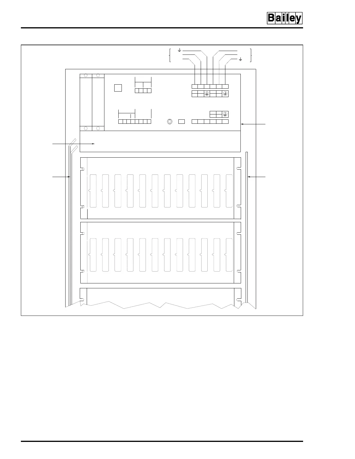
To mount the module:
NOTE:
Be careful not to bump switch S1 when installing the AC
transfer module. Accidentally moving the switch to the 240 position
will cause the module to go into error mode.
1. Grasp the sides of the faceplate.
2. Line up circuit board edges with card guides in the power
entry panel opening.
3. Slide the module in until it locks in place.
Figure 3-3. IEPEP03 Power Entry Panel, Rear View
12 6543
TP25378B
INPUT
POWER
BUS BAR
SYSTEM
POWER
BUS BAR
FAN
ASSEMBLY
AT M
SLOT
BMM
SLOT
J2
TB4
TB2J1
120 VAC
240 VAC
120 VAC
240 VAC
TB1 1 2 6543
1
15
2
26
CH1
+–
PWR
SYS
+–
BUS
VOLT
+–
CH2
+–
AUX BUS
MONITOR
STATUS
IN
1COM2
OUT
ALARMS
GND
FAN
OUT
AC OUT
L
L1
L
L1
L
L1
N
L2
N
L2
N
L2
3
37
4
48
TB3
POWER ENTRY
PAN EL
IEPEP03
ROW 0
AUX.POWER INPUT
120/240 VAC 50/60 HZ
MAIN POWER INPUT
120/240 VAC 50/60 HZ
L(L1)
N (L2)
N(L2)
L(L1)
Artisan Technology Group - Quality Instrumentation ... Guaranteed | (888) 88-SOURCE | www.artisantg.com