9424200994 Rev N 101
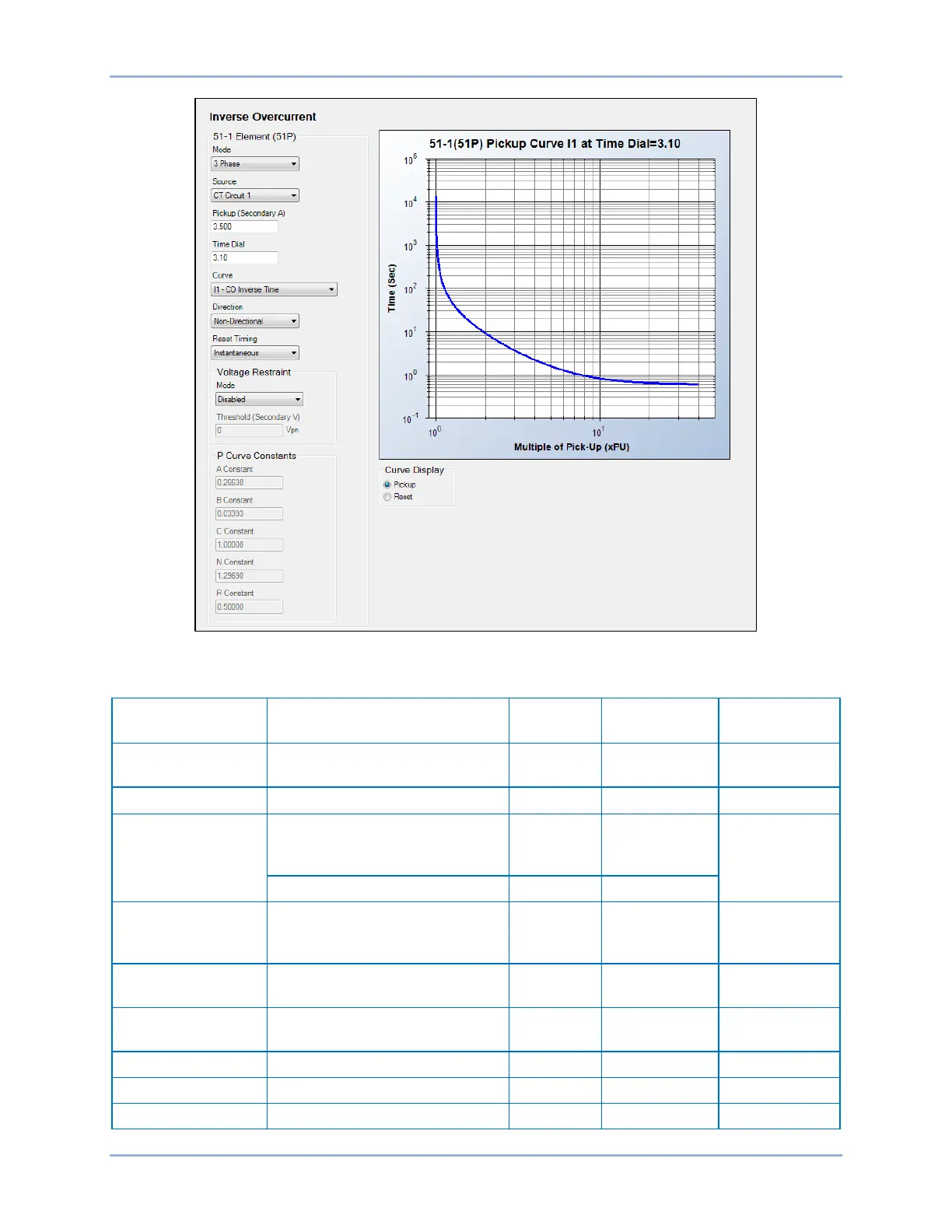
Figure 65. Inverse Overcurrent Settings Screen
Table 36. Operational Settings
Setting Range Increment
Default
Mode
Disabled, IA, IB, IC, 3 Phase,
3I0, I1, I2, IG, or Unbalance
n/a n/a Disabled
CT Circuit 1 or CT Circuit 2
Pickup
0 or 0.1 to 3.2 (1A CTs)
varies amps
0
2 to 100 (Unbalance mode)
Time Dial
0 to 1 (IEC curves only)
varies units 0
Curve
See the Time Curve
Characteristics chapter.
n/a n/a S1
Direction
Forward, Reverse, or Non-
Directional
n/a n/a
Integrating or Instantaneous
BE1-11g Inverse Overcurrent (51) Protection