9424200994 Rev N 233
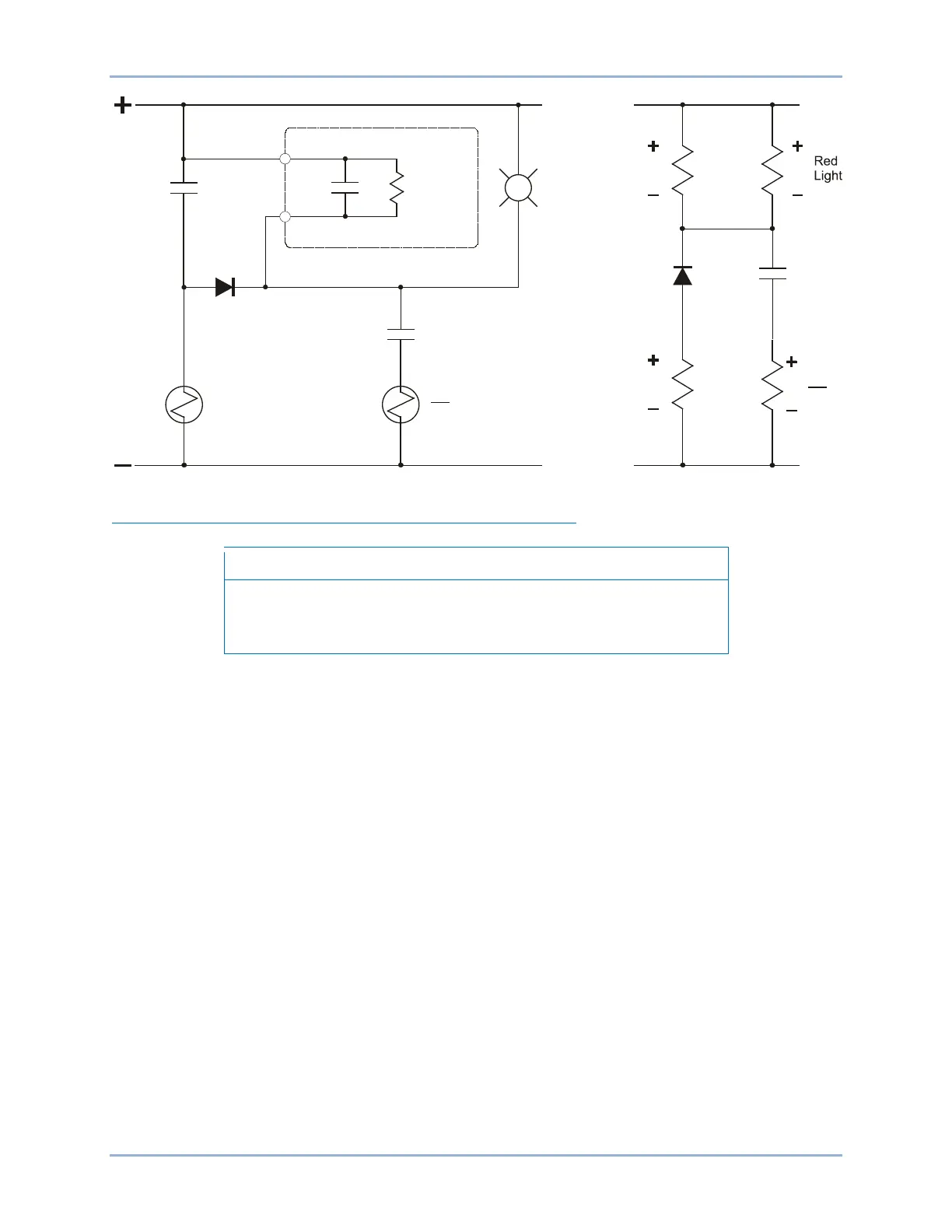
Figure 166. TCM with Other Devices
Trip Circuit Monitor (52TCM) Enable/Disable Jumper (J Type Case)
A BE1-11g in a J type case is delivered with the trip circuit monitor
enabled (TCM jumper connected). Read the following paragraphs
before placing the BE1-11g in service.
The trip circuit monitor draws a small amount of current, even when the contact is open. See Table 88 for
actual values. If the output is connected to light loads or digital inputs, it may be necessary to remove the
jumper to prevent the trip circuit monitor from activating those inputs.
The following paragraphs describe how to locate and connect/remove the trip circuit monitor jumper:
1. The trip circuit monitor jumper is located behind the rear terminal block that is used for OUT1
through OUTA and voltage sensing input connections. Using a 7/64” hex tool, remove the rear
terminal block. Observe all electrostatic discharge (ESD) precautions when handling the
BE1-11g.
2. Locate the jumper terminal block that is mounted on the left side of the circuit board. The terminal
block has four pins. With the jumper as installed at the factory, the jumper should be connected
across pins 1 and 2 (left side) when viewed from the back of the unit. This jumper configuration
enables the trip circuit monitor. Figure 167 illustrates the location of the jumper terminal block as
well as the position of the jumper connected.
3. To disable the trip circuit monitor, remove the jumper from the two pins using needle-nose pliers.
Use care when removing the jumper so that no components are damaged. Retain the jumper for
enabling the trip circuit monitor in the future.
4. After removing the jumper to disable the trip circuit monitor, reinstall the rear terminal block.
5. Tighten the screws using a 7/64” hex tool. A torque of 10 in-lbs (1.12 N•m) is recommended.
OUT1
TRIP
CIRCUIT
CONTINUITY
MONITOR
C1
C2
BE1-11g
Other
Relays
52a
TCM
V
V
Trip
Trip
62X
52
TC
62X
P0057-41
R
V
V
52
TC
BE1-11g Trip Circuit Monitor (52TCM)