9424200994 Rev N 13
Figure 2. Front Panel Label Example
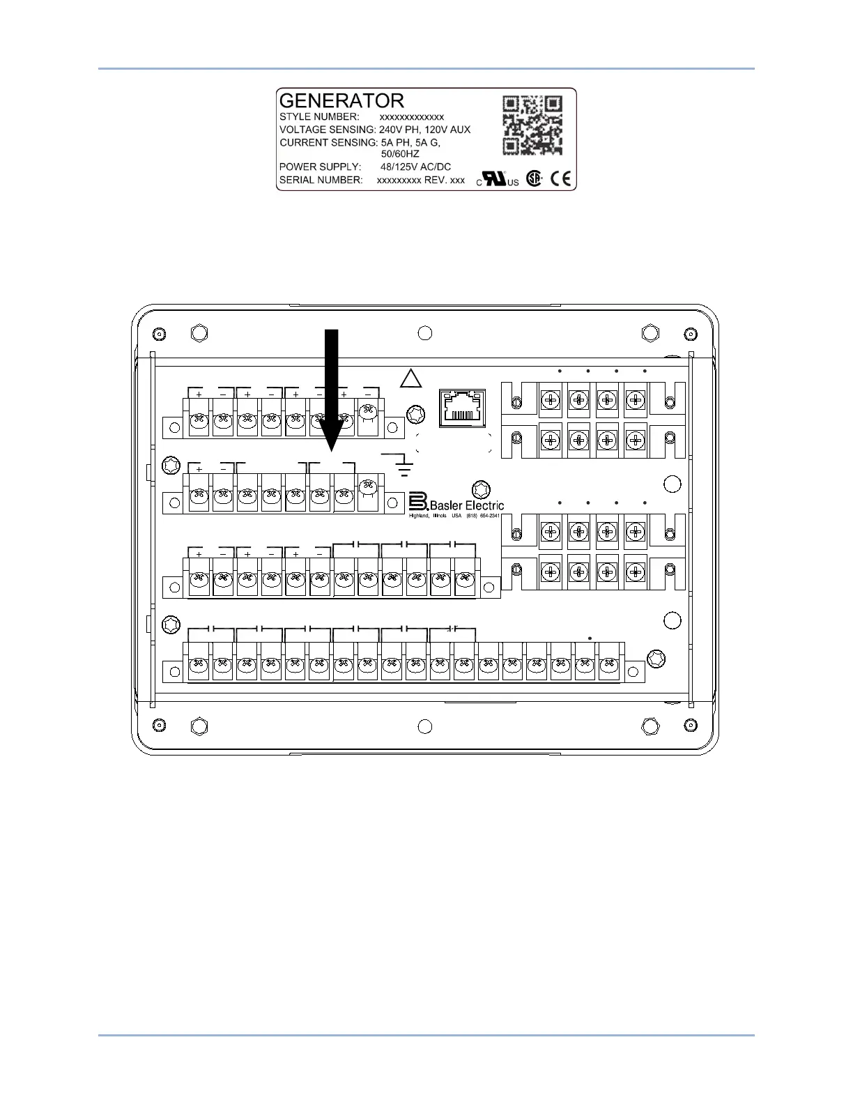
Connect rear terminals A6, A7, and A8 (ground) to a power supply. Figure 3 shows the rear terminals of
the BE1-11g in a J type case. Figure 4 shows the rear terminals of the BE1-11g in an H or P type case.
Apply operating power consistent with the nominal power supply values listed on the front-panel label.
Wait until the boot sequence is complete.
Figure 3. PWR Rear Terminals (J Type Case)
ETHERNET
!
WARNING
BE1-11
C12C11C10C9C8C7C6C5C4C3C2C1 C13 C14 C15 C16 C17 C18
V
A
OUT 2 OUT 3 OUT 4 OUT 5OUT 1 ALARM V
B
V
C
V
X
V
X
N
E12E11E10E9E8E7E6E5E4E3E2E1
OUT 8 OUT 7
IN5 IN6
IN7
OUT 6
A8A7A6A5A4A3A2A1
IRIG PWR
CA B
COM2 RS-485
GND
B8B7B6B5B4B3B2B1
IN1 IN2
IN3
IN4
D1 D3 D5 D7
I
A1
I
B1
I
C1
I
G1
I
A1
D2 D4 D6 D8
I
B1
I
C1
I
G1
I
A2
F2 F4 F6 F8
I
B2
I
C2
I
G2
F1 F3 F5 F7
I
A2
I
B1
I
C2
I
G2
P0061-43
BE1-11g Quick Start