20 9424200994 Rev N
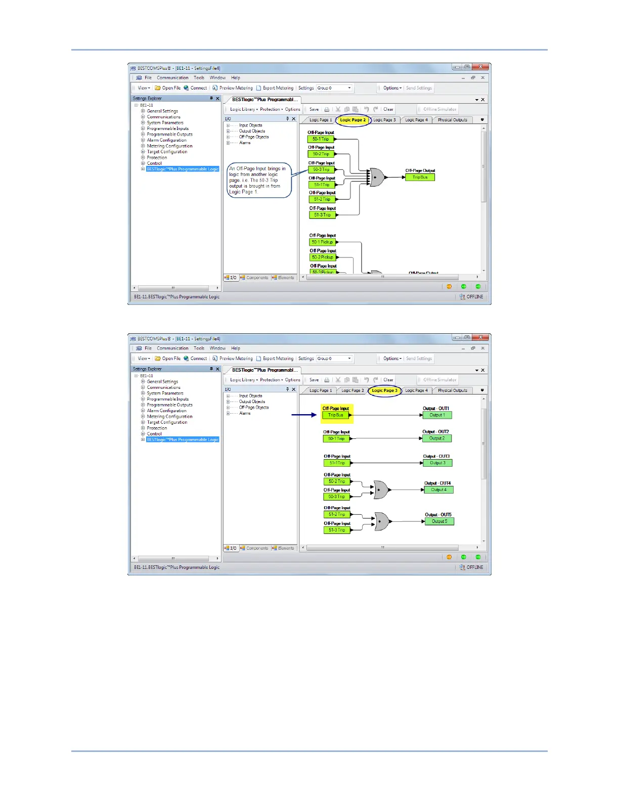
Figure 15. BESTlogicPlus Logic Page 2
Figure 16. BESTlogicPlus Logic Page 3
Step 10: In this step, the Pickup output of the 50-3 element is connected to Output 4. When the Pickup
output of the 50-3 element is true, the label of Output 4 is displayed in the fault report and/or
sequence of events report. The label is named in Step 12. Click the Logic Page 1 tab and then
click the I/O tab at the bottom. Expand Output Objects and then Physical Outputs. Click and
drag OUT4 over to the logic diagram. Click on the Pickup output of the 50-3 element and drag it
to the input of OUT4 to make a connection. Refer to Figure 17.
Quick Start BE1-11g