9424200994 Rev N 21
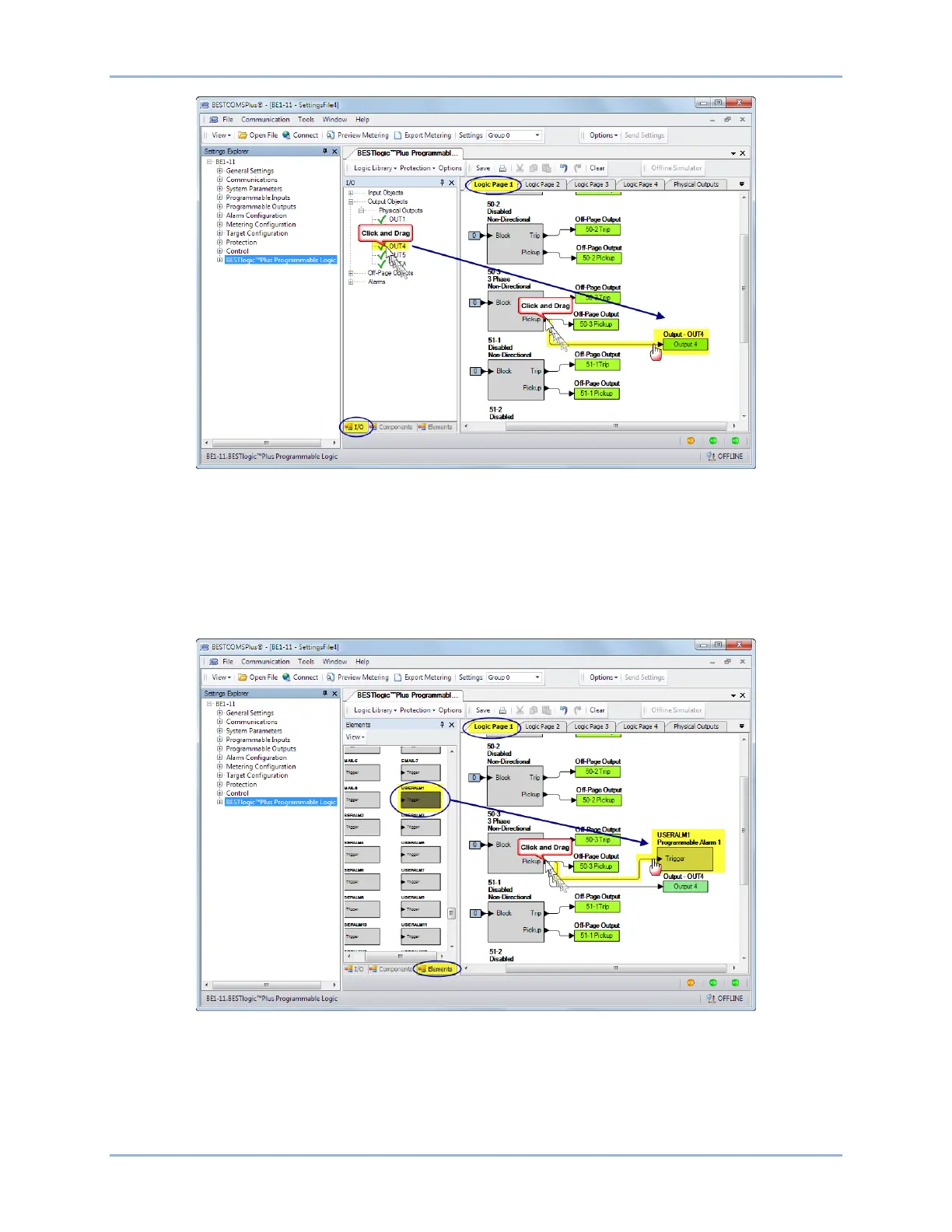
Figure 17. BESTlogicPlus Programming OUT4
Step 11: In this step, the Pickup output of the 50-3 element is connected to User Alarm 1. When the
Pickup output of the 50-3 element is true, the label of the user alarm is displayed on the Alarms
screen on the front-panel display and in the fault report and/or sequence of events report. The
label is named in Step 13. Click the Logic Page 1 tab and then click the Elements tab at the
bottom. Locate the User Alarm 1 element. Click and drag USERALM1 over to the logic diagram.
Click on the Pickup output of the 50-3 element and drag to the input of USERALM1 to make a
connection. Refer to Figure 18.
Figure 18. BESTlogicPlus Programming User Alarm 1
Step 12: Click the Save button to save the logic to BESTCOMSPlus memory for later inclusion in the
settings file. See Figure 19.
BE1-11g Quick Start