9424200994 Rev N 27
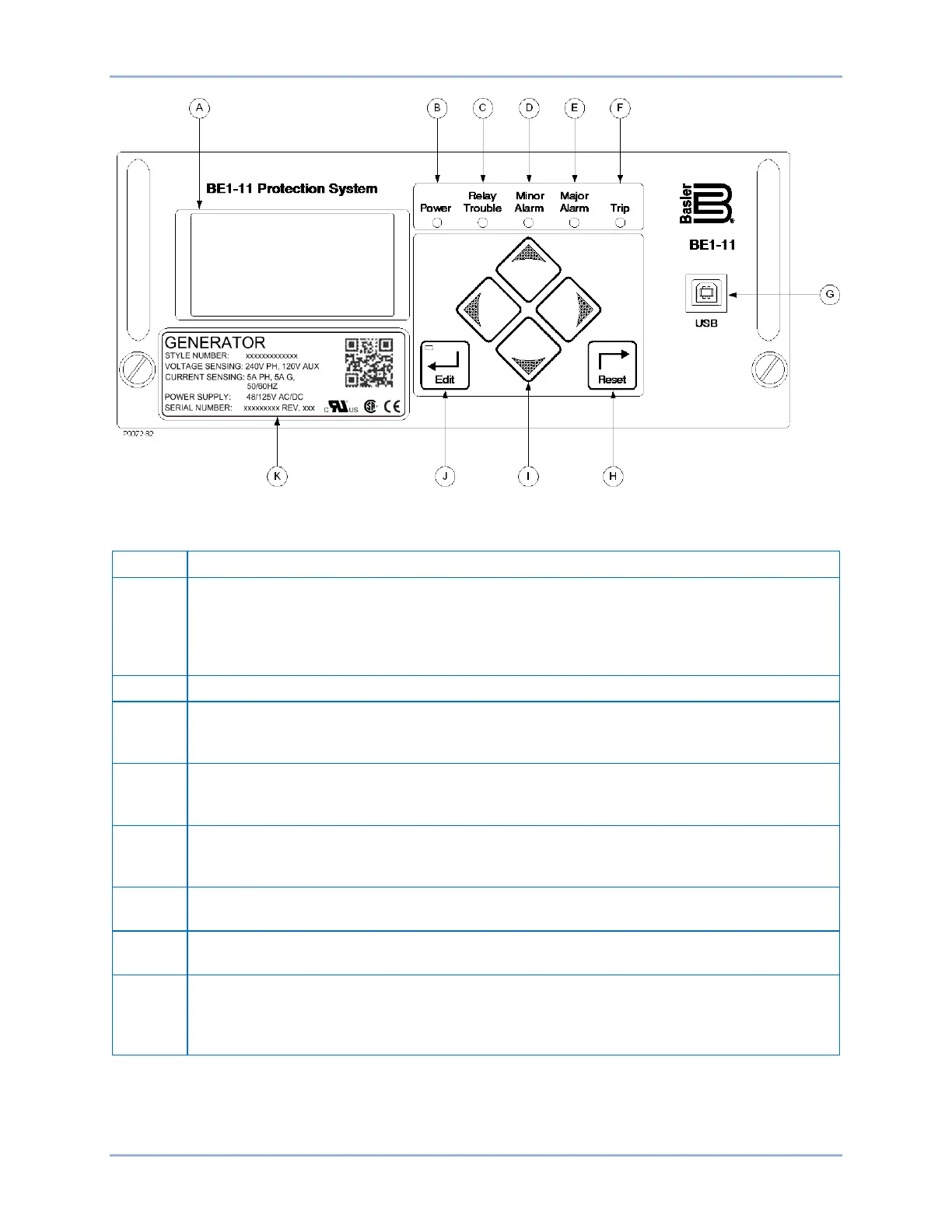
Figure 24. Front Panel (H or P Type Case)
Table 3. Front Panel Descriptions (H or P Type Case)
Display – 64 x 128 dot pixels liquid crystal display (LCD) with backlighting. The LCD is the
primary source for obtaining information from the BE1-11g or when locally setting the
BE1-11g. Information such as targets, metering values, demand values, communication
parameters, and diagnostic information is provided by the LCD. Information and settings are
Power Indicator – This green LED lights when operating power is applied to the BE1-11g.
Relay Trouble Indicator – This red LED lights momentarily during start-up and lights
continuously when a BE1-11g failure is detected. The Contact Inputs and Outputs chapter
provides a complete description of all BE1-11g failure alarm diagnostics.
Minor Alarm, Major Alarm Indicators – These red LEDs light to indicate that a programmable
alarm has been set. Each indicator can be programmed to annunciate one or more
conditions. The Alarms chapter provides detailed information about programming alarms.
Trip Indicator – A flashing red Trip LED indicates that a protective element is picked up. A
continuously lit LED indicates that a trip output is closed. This red LED is sealed in if a
protective trip has occurred and targets are displayed.
USB – This universal serial bus port can be used to communicate with the BE1-11g using
BESTCOMSPlus.
Reset Pushbutton – Pressing this button resets the Trip LED, sealed-in Trip Targets, Peak
Demand Currents, and Alarms.
Scrolling Pushbuttons – Use these four switches to navigate (UP/DOWN/LEFT/RIGHT)
through the LCD menu tree. When in Edit mode, the LEFT and RIGHT scrolling
pushbuttons select the variable to be changed. The UP and DOWN scrolling pushbuttons
BE1-11g Controls and Indicators