398 9424200994 Rev N
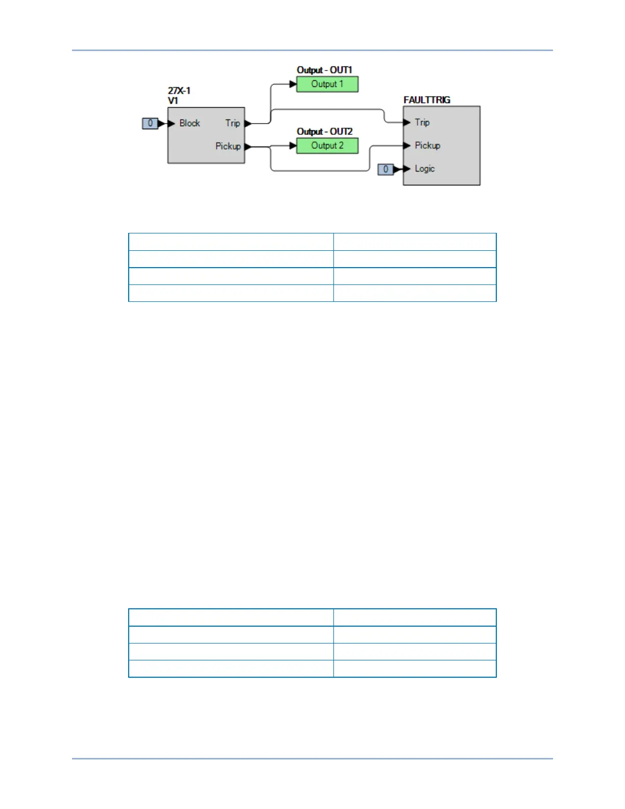
Figure 281. BESTlogicPlus Settings (V1 Mode)
Table 143. Pickup Test Settings (V1 Mode)
Step 4: Prepare to monitor the 27X-1 function operation. Operation can be verified by monitoring OUT2
(see Figure 281).
Step 5: Connect and apply a 240 Vac, single-phase voltage source to terminals C13 (A-phase) and C16
(neutral). For a single-phase input test, V1 = A-phase voltage / 3. Therefore, the BE1-11g
should pick up at a value of three times the setting value when applying only a single-phase
input. For example, to determine the pickup voltage value required for a BE1-11g with a pickup
setting of 78, it would require 78 times 3 or 234 volts of input voltage.
Step 6: Slowly decrease the A-phase voltage until OUT2 closes and record the pickup. Verify that there
is a 27X-1-V1 target on the front-panel display. Slowly increase the voltage until OUT2 opens
and record the reset. Reset the target.
Step 7: Verify the pickup and reset accuracy at 120 Vac for a pickup setting of 38 V (114 Vac on test
set) and 70 Vac for a pickup setting of 22 V (66 Vac on test set) as listed in Table 143. Record
the results.
Step 8: (Optional.) Repeat steps 1 through 7 for the B-phase and C-phase voltage inputs.
Step 9: (Optional.) Repeat steps 1 through 8 for settings group 1, 2, and 3.
Step 10: (Optional.) Repeat steps 1 through 9 for 27X-2, 27X-3, and 27X-4.
Timing Verification (V1 Mode)
Step 1: Use BESTCOMSPlus to open the Protection, Voltage, Undervoltage (27X-1) screen and send
the first row of test settings in Table 144 to the BE1-11g for settings group 0.
Table 144. Timing Test Settings (V1 Mode)
Step 2: Prepare to monitor the 27X-1 timings. Timing accuracy is verified by measuring the elapsed
time between a sensing voltage change and OUT1 closing.
Step 3: Connect and apply a 120 Vac, single-phase voltage source to terminals C13 (A-phase) and C16
(neutral).
Step 4: Step the voltage down to 110 volts. Measure the time delay and record the result.
Auxiliary Undervoltage (27X) Test BE1-11g

 Loading...


