448 9424200994 Rev N
• Fault recording is enabled.
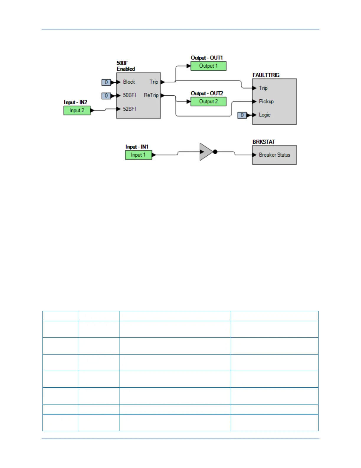
• Breaker Status is closed with /IN1.
Figure 300. BESTlogicPlus Settings (BFI52 Contact Initiate)
Step 3: IN1 is used to simulate breaker status as supplied by a “b” contact from the circuit breaker. With
no wetting voltage applied to BE1-11g input IN1, the BE1-11g considers the breaker closed
because of the /IN1 designation at the breaker status input of the breaker failure element. A
switched wetting voltage at IN2 is used to simulate an external BFI52 initiate contact for starting
the Breaker Failure Timer. This input is also used to start the test set timer and OUT1 of the
BE1-11g is used to stop the test set timer. OUT2 should be monitored to verify operation of the
re-trip circuit upon breaker failure initiate.
Step 4: With no wetting voltage applied to BE1-11g input IN1, switch on the wetting voltage to IN2 and
measure the operate time. Record the result.
Step 5: Apply wetting voltage to IN1 and repeat step 4. There should be no operation.
Step 6: Repeat step 3 with the delay timer set at 200 ms and 300 ms. Record the results.
The following tests are for Current Supervised BE1-11g trip initiates. Any or all BE1-11g trips can be
used: 50 Trip, 51 Trip, etc. For ease of testing, the 50-1 Trip variable will be used in the following tests.
Step 7: Use BESTCOMSPlus to send the operational settings in Table 194 to the BE1-11g. Reset all
targets.
Table 194. Operational Settings (BFI50 Current Supervised BE1-11g Trip Initiate)
Protection, Current, Breaker Fail (50BF)
Protection, Current, Breaker Fail (50BF)
Protection, Current, Breaker Fail (50BF)
Sets ground pickup to 1 A
Protection, Current, Breaker Fail (50BF)
Protection, Current, Breaker Fail (50BF)
Sets delay timer to 100 ms
Target Configuration, Targets
Alarm Configuration, Alarms
Sets 50BF BFI alarm for Minor
Alarm
Breaker Fail (50BF) Test BE1-11g