452 9424200994 Rev N
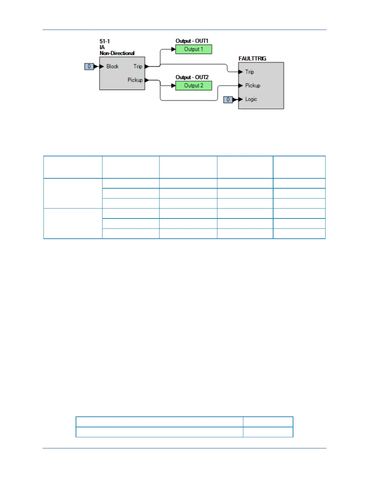
Figure 302. BESTlogicPlus Settings (Phase Mode)
Step 3: Use BESTCOMSPlus to open the Protection, Current, Inverse Overcurrent (51-1) screen and
send the low range test settings (minimum pickup setting) to the BE1-11g for your sensing input
type in Table 197.
Table 197. Pickup Test Settings (Phase Mode)
Sensing Input
Type
Range Pickup Setting Time Dial Time Curve
5 A
1 A
Step 4: Prepare to monitor the 51-1 function operation. Operation can be verified by monitoring OUT2
(see Figure 302).
Step 5: Connect a current source to terminals D1 and D2 (A-phase). Note that mode can be set for IA,
IB, IC, or 3 phases. Test is conducted on IA.
Step 6: Slowly increase the A-phase current until OUT2 closes and record the pickup. Verify that there
is a 51-1-A target on the front-panel display. Slowly decrease the applied current until OUT2
opens and record the dropout.
Step 7: Repeat step 6 for the middle and high range pickup settings for your sensing input type. Record
the results.
Step 8: (Optional.) Repeat steps 1 through 7 for phase B and phase C. Note: Be sure to change
Element Mode and enable proper target for each phase being tested.
Step 9: (Optional.) Repeat steps 1 through 8 for settings group 1, 2, and 3.
Step 10: (Optional.) Repeat steps 1 through 9 for 51-2, 51-3, 51-4, 51-5, 51-6, and 51-7.
Step 11: (Optional.) Repeat steps 1 through 10 with CT Circuit 2 as the source for protection systems
equipped with two sets of CTs. In step 5, replace D1 with F1, D2 with F2, etc.
Timing Verification (Phase Mode)
Step 1: Use BESTCOMSPlus to open the Protection, Current, Inverse Overcurrent (51-1) screen and
send the test settings in Table 198 to the BE1-11g for settings group 0.
Table 198. Timing Test Settings (Phase Mode)
0.5 A (5 A sensing), 0.1 A (1 A sensing or SEF)
Inverse Overcurrent (51) Test BE1-11g

 Loading...