478 9424200994 Rev N
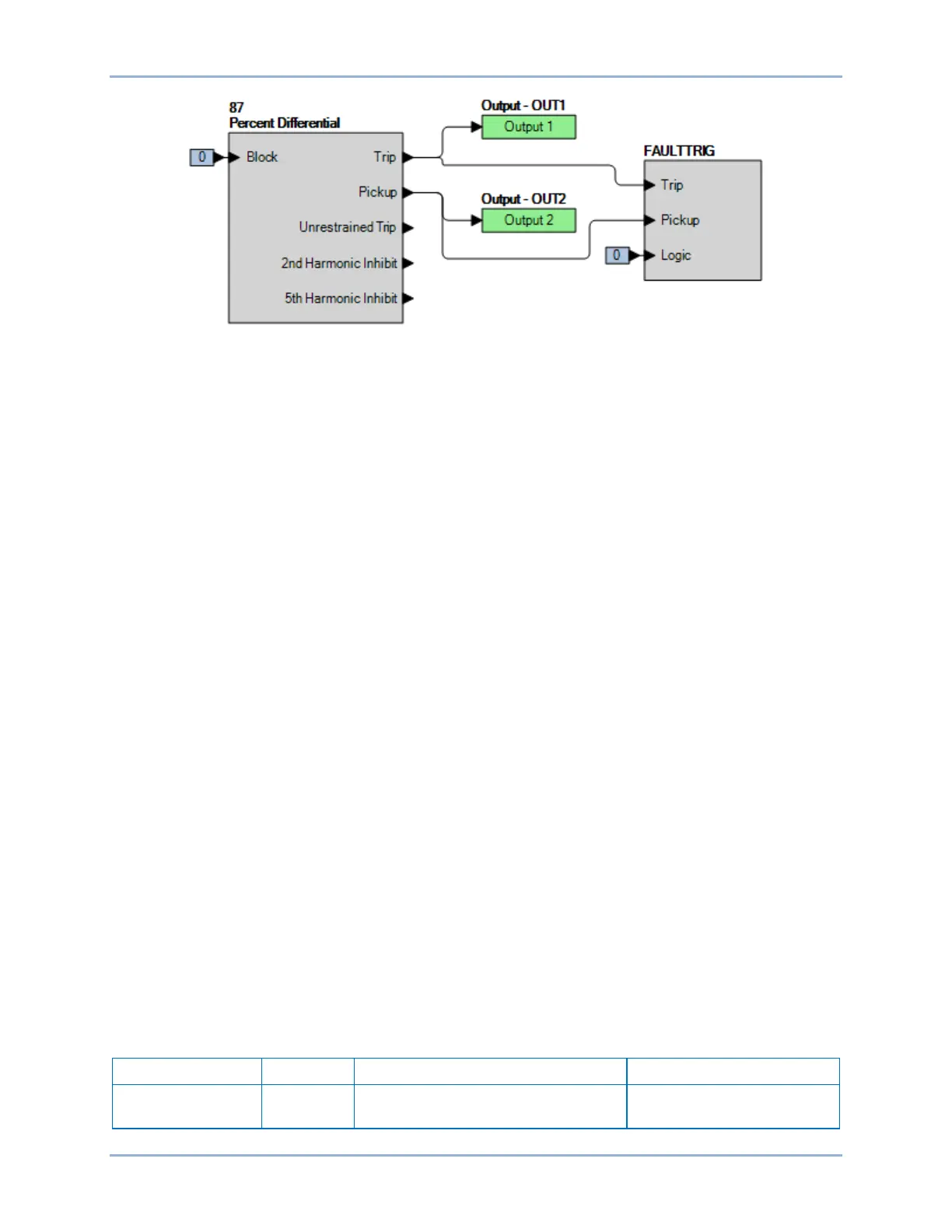
Figure 307. BESTlogicPlus Settings (87R)
Step 8: Slowly decrease the A-phase current in CT circuit 1 or 2 until OUT2 closes and record the
pickup. This should occur at 0.30 A ±0.05 A. Verify that there is an 87A target on the front-panel
display.
Step 9: Slowly increase the A-phase current in CT circuit 1 or 2 until OUT2 reopens and record the
dropout. See the functional test report for acceptable ranges.
Step 10: To test the Restraint Slope 1 setting, connect two balanced three-phase current sources to the
BE1-11g in ABC rotation: 3.0∠0°, 3.0∠–120°, 3.0∠120° amps to terminals D1 through D6 and
3.0∠180°, 3.0∠60°, 3.0∠–60° amps to terminals F1 through F6 (1.5x tap).
Step 11: Slowly increase the A-phase current in CT circuit 1 or 2 until OUT2 closes and record the
pickup. This should occur at 3.75 A ±0.08 A. Verify that there is an 87A target on the front-panel
display.
Step 12: Reset to the current levels in Step 9 and reset all targets.
Step 13: Slowly decrease the A-phase current in CT circuit 1 or 2 until OUT2 closes and record the
pickup. This should occur at 2.40 A ±0.05 A. Verify that there is an 87A target on the front-panel
display.
Step 14: To test the Restraint Slope 2 setting, connect two balanced three-phase current sources to the
BE1-11g in ABC rotation: 6.5∠0°, 6.5∠–120°, 6.5∠120° amps to terminals D1 through D6 and
6.5∠180°, 6.5∠60°, 6.5∠–60° amps to terminals F1 through F6 (3.25x tap).
Step 15: Slowly increase the A-phase current in CT circuit 1 or 2 until OUT2 closes and record the
pickup. This should occur at 8.83 A ±0.18 A. Verify that there is an 87A target on the front-panel
display.
Step 16: Reset to the current levels in Step 12 and reset all targets.
Step 17: Slowly decrease the A-phase current in CT circuit 1 or 2 until OUT2 closes and record the
pickup. This should occur at 5.10 A ±0.10 A. Verify that there is an 87A target on the front-panel
display.
Step 18: (Optional.) Repeat Steps 1 through 17 for the B-phase and C-phase current inputs.
Step 19: (Optional.) Repeat Steps 1 through 18 for settings group 1, 2, and 3.
Pickup Verification (Average Restraint)
Step 1: Use BESTCOMSPlus to send the operational settings in Table 220. Reset all targets.
Table 220. Operational Settings (87R - Average)
System Parameters, Power System
Sets the nominal secondary
sensing voltage to 69.3 V
Phase Current Differential (87) Test BE1-11g