488 9424200994 Rev N
Compensation
System Parameters, Transformer
Setup
winding zero sequence
1 Diff. Circuit
System Parameters, Transformer
Setup
Establishes circuit 1 on the
primary side of the
transformer. For report
System Parameters, Transformer
Setup
Sets the phase rotation of
circuit 1 for ABC
Relationship
System Parameters, Transformer
Setup
Sets A-phase in circuit 1
equal to the phase
relationship setting for
Protection, Current, Neutral
Differential (87N-1)
Enables the neutral
differential element
Protection, Current, Neutral
Differential (87N-1)
current required for pickup
Protection, Current, Neutral
Differential (87N-1)
Sets the time to trip after a
pickup to 100 ms
Coefficient
Protection, Current, Neutral
Differential (87N-1)
Sets the sensitivity of the
directional sensing by
Protection, Current, Neutral
Differential (87N-1)
phase with 3I0 for internal
Protection, Current, Neutral
Differential (87N-1)
Sets the differential zone
with CT1 and IG1
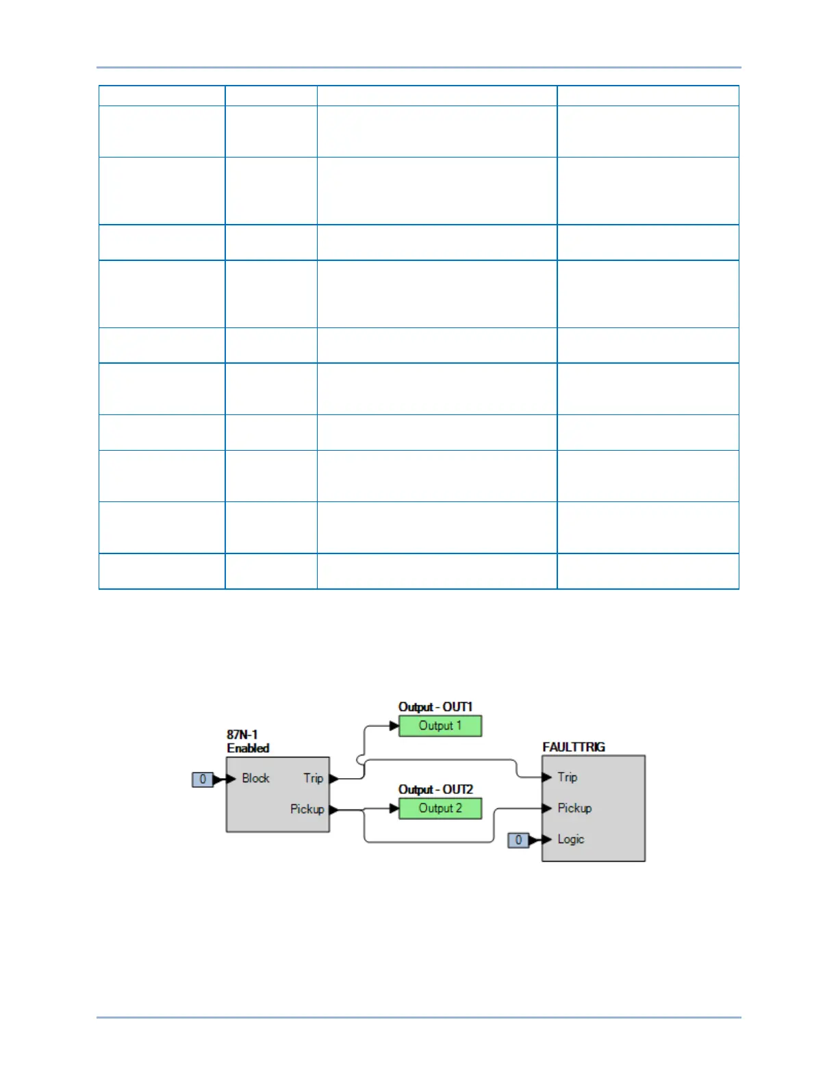
Step 2: Use BESTCOMSPlus to configure the BESTlogicPlus programmable logic shown in Figure 309.
• Blocking is disabled.
• OUT1 closes for 87N-1 Trip.
• OUT2 closes for 87N-1 Pickup.
• Fault recording is enabled.
Figure 309. BESTlogicPlus Settings
Step 3: Prepare to monitor the 87N-1 function operation. Operation can be verified by monitoring OUT2
(see Figure 309).
Step 4: Connect a single-phase 60-Hz current source to terminals D1 and D2 (CT1 A-phase): 3.0 A
∠0°. Connect a single-phase current source to terminals D7 and D8 (IG input): 3.0 A ∠180°.
Verify that Iop is around zero amps.
Neutral Current Differential (87N) Test BE1-11g