514 9424200994 Rev N
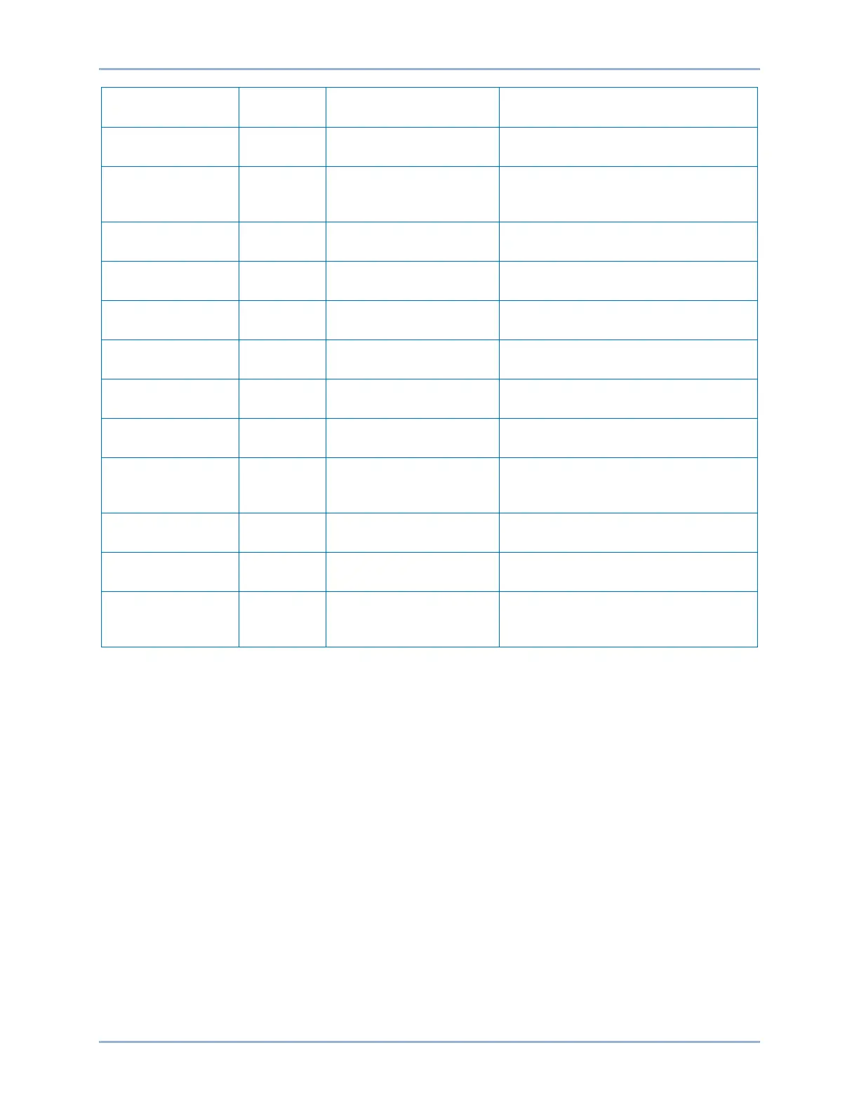
Setting Value
Description
Control, Synchronizer
(25A)
Enables 25A function for PLL
operation
(%)
(25A)
Sets the voltage difference
requirement to 15% of the nominal
Control, Synchronizer
(25A)
Sets the allowable slip frequency to
0.5 Hz
Control, Synchronizer
(25A)
Sets the minimum allowable slip
frequency to 0.2 Hz
Control, Synchronizer
(25A)
Sets the maximum allowable slip
frequency to 1.5 Hz
Breaker Close
Angle (degrees)
Control, Synchronizer
(25A)
Sets the maximum slip angle to 20°
Control, Synchronizer
(25A)
Sets number of breaker close attempts
to 1
Sync Fail
Activation Delay (s)
Control, Synchronizer
(25A)
Sets the activation delay for the sync
fail alarm to 5 seconds
Volt Dest
(25A)
Requires voltage at the phase
terminals to be greater than the
voltage at the Vx terminals by 0.5%
Control, Synchronizer
(25A)
Sets the voltage control output mode
to continuous
Control, Synchronizer
(25A)
Sets the frequency control output
mode to continuous
Compensation
(25A)
Disables angle compensation
Step 2: Use BESTCOMSPlus to configure the BESTlogicPlus Programmable Logic shown in
Figure 315.
• Blocking is disabled.
• 25A is initiated.
• OUT1 closes for 25A Close Breaker.
• OUT2 closes for Lower Freq.
• OUT3 closes for Raise Freq.
• OUT4 closes for Lower Voltage.
• OUT5 closes for Raise Voltage.
• OUT6 closes for synchronization criteria met.
• OUT7 closes for voltage monitor criteria met.
• OUT8 closes for breaker open after maximum close attempts.
• Output Alarm closed during synchronizing.
• Event recording is enabled.
Step 3: Prepare to monitor the Voltage Difference function operation. Operation can be verified by using
BESTCOMSPlus to monitor the status of Metering Explorer, Status, Digital Points (1536-1567),
25A Volt Diff.
Synchronizer (25A) Test BE1-11g

 Loading...


