9424200994 Rev N 515
`
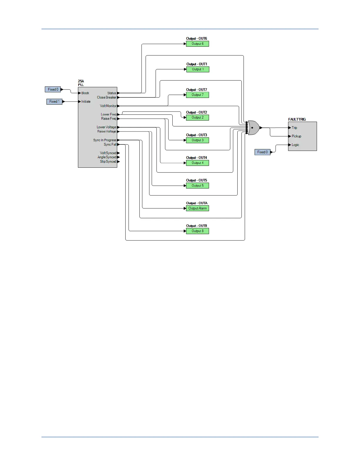
Figure 315. BESTlogicPlus Settings 1 (25A)
Step 4: Connect a balanced, three-phase voltage source of 69.28 Vpn, 60 Hz to BE1-11g terminals C13
(A-phase), C14 (B-phase), C15 (C-phase), and C16 (neutral). Apply a single-phase, 60-hertz
voltage of 69.28 Vpn, ∠0°, to terminals C17 (Vx-phase) and C18 (Vx-neutral). The 25A Volt Diff
digital point should light.
Step 5: Slowly increase the line voltage until the 25A Volt Diff digital point turns off. This should happen
at 79.67 V, ±1 V. Record the result.
Step 6: Uncheck the Voltage Source > Volt Dest checkbox on the Synchronizer (25A) settings screen
and send the settings to the BE1-11g.
Step 7: Decrease the voltage until the 25A Volt Diff digital point turns on (69.28 V). Record the result.
Step 8: Slowly decrease the line voltage until the 25A Volt Diff digital point turns off. This should happen
at 58.89 V ±1 V. Record the result.
Step 9: Increase the voltage until the 25A Volt Diff digital point turns on (69.28 V). Record the result.
Step 10: (Optional) Repeat steps 2 through 9 for settings group 1, 2, and 3.
Slip Frequency Verification
Step 1: Use BESTCOMSPlus to monitor the status of Metering Explorer, Status, Digital Points (1536-
1567), 25A Slip Diff.
Step 2: Connect a balanced, three-phase voltage source of 69.28 Vpn, 60 Hz to BE1-11g terminals C13
(A-phase), C14 (B-phase), C15 (C-phase), and C16 (neutral). Apply a single-phase, 60-hertz
BE1-11g Synchronizer (25A) Test


 To Next Page