524 9424200994 Rev N
System Parameters, Sensing
Transformers
Sets auxiliary VT
connection to AN.
System Parameters, Power
System
Sets nominal phase voltage
to 100 V.
System Parameters, Power
System
Sets nominal auxiliary
voltage to 100 V.
Control, Synchronizer (25A)
Enables the 25A function.
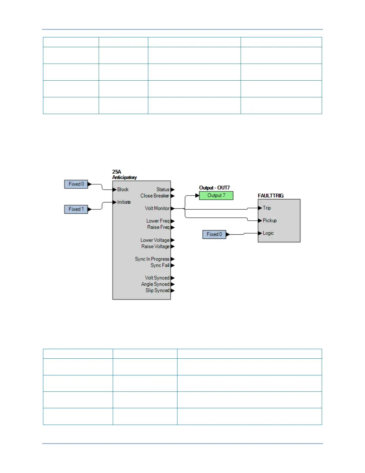
Step 2: Use BESTCOMSPlus to configure the BESTlogicPlus Programmable Logic shown in
Figure 317.
• Blocking is disabled.
• 25A is initiated.
• OUT7 closes for voltage monitor criteria met.
• Event recording is enabled.
Figure 317. BESTlogicPlus Settings 3 (25A)
Step 3: Use BESTCOMSPlus to open the Control, Synchronizer (25A) screen and send the test settings
in Table 238 to the BE1-11g.
Table 238. Time Pickup Test Settings (25VM)
Setting Value Description
25 Voltage Monitor Live
Voltage
90%
Sets live voltage to 90 V (90% of nominal, nominal
= 100 V).
25 Voltage Monitor
Dead Voltage
55%
Sets dead voltage to 55 V (55% of nominal, nominal
= 100 V).
25 Voltage Monitoring
Drop Out Delay
0 Sets drop out delay to 0.
25 Voltage Monitor
Logic
Check boxes as
shown in Figure 318.
Enable: Dead Line/Dead Aux, Dead Line/Live Aux,
Live Line/Dead Aux.
Synchronizer (25A) Test BE1-11g