528 9424200994 Rev N
Figure 319. BESTlogicPlus Settings
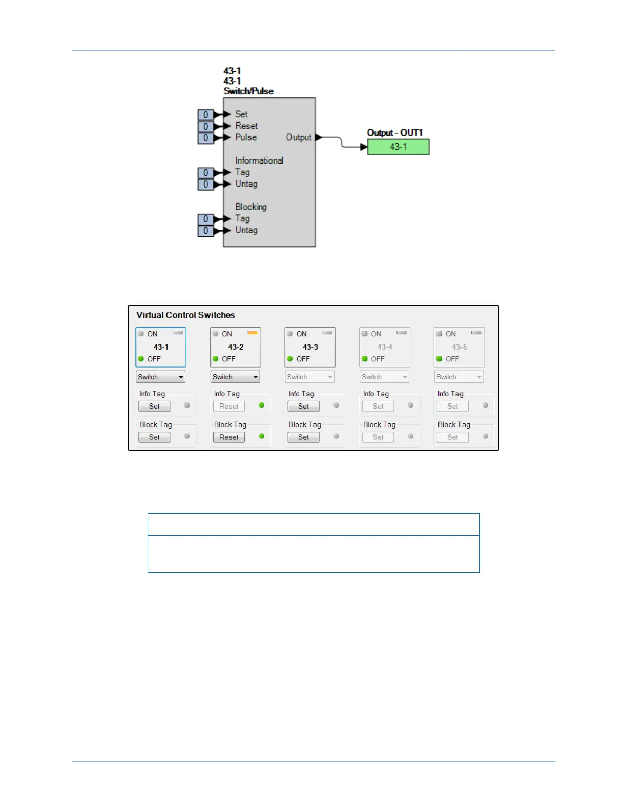
Step 4: Use the Metering Explorer of BESTCOMSPlus to open the Control, Virtual Switches tree branch
(Figure 320). Using select-before-operate, perform the following steps to control a virtual switch.
Figure 320. BESTCOMSPlus Virtual Switches Control Screen
Step 5: Click the 43-1 button to select it. Login may be required. The On or Off indicator (current state)
will begin to flash.
If step 6 is not performed within 25 seconds of step 5, the indicator will
stop flashing and the 43-1 button will have to be selected again.
Step 6: Click on the 43-1 button a second time to operate it. After clicking Yes, the On or Off indicator
(previous state) will stop flashing and the On or Off indicator (current/new state) will light.
Step 7: Verify that OUT1 contact closes and remains closed.
Step 8: Repeat steps 5 and 6 to change the state of the 43-1 switch to OFF. Verify that OUT1 contact
opens and remains open.
Step 9: (Optional.) Repeat steps 1 through 8 for 43-2, 43-3, 43-4, and 43-5.
Step 10: (Optional.) Repeat steps 1 through 9 for settings group 1, 2, and 3.
Switch Mode
Step 1: Change the 43-1 element mode to Switch.
Step 2: Prepare to monitor the virtual switch operation. An ohmmeter or continuity tester can be used to
monitor the contact status of OUT1.
Virtual Control Switches (43) Test BE1-11g