532 9424200994 Rev N
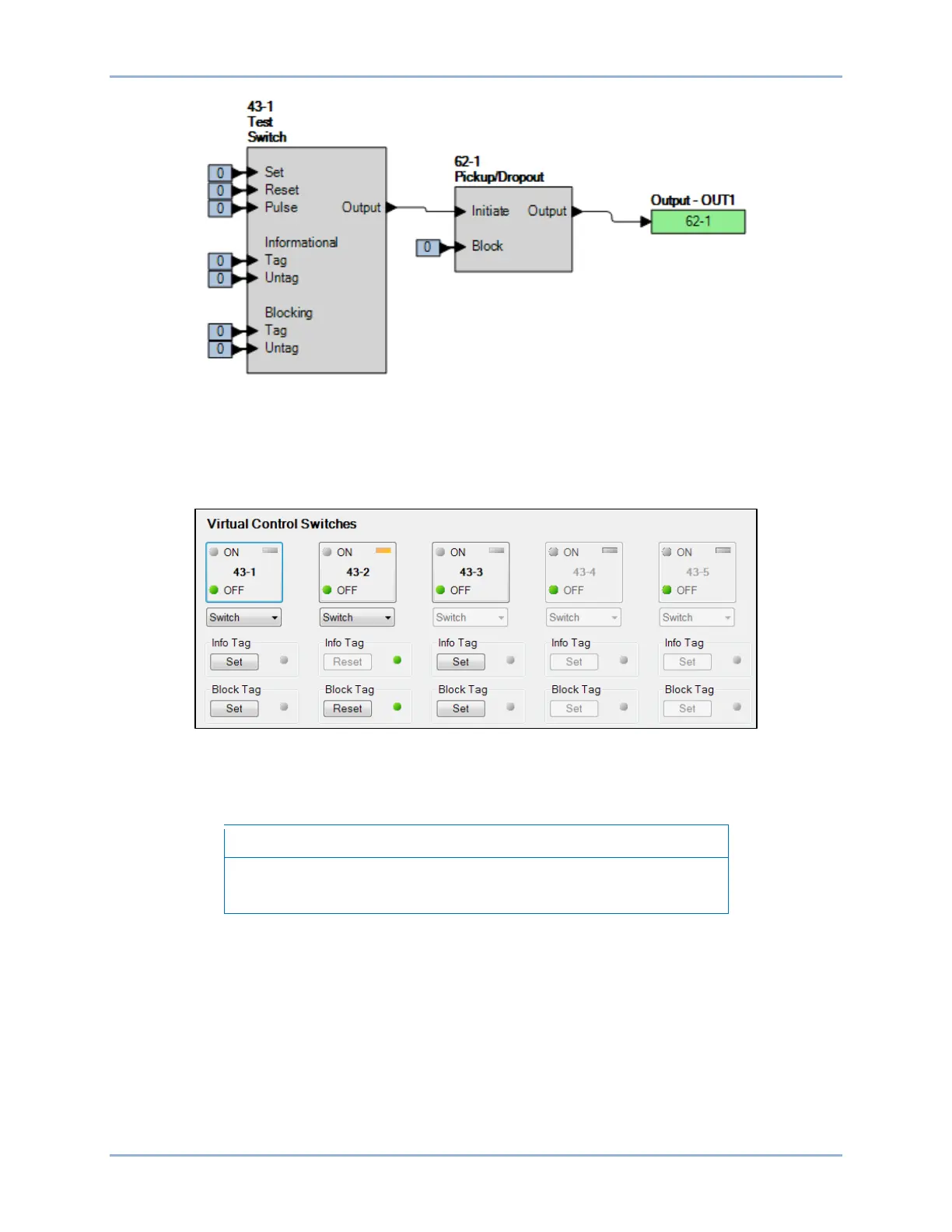
Figure 321. BESTlogicPlus Settings
Step 3: Steps 4 through 6 will initiate the 62-1 timer by changing the 43-1 switch state to ON (logic 1).
Once initiated, the 62-1 timer will force an output based on the 400 ms pickup time setting.
Step 4: Use the Metering Explorer of BESTCOMSPlus to open the Control, Virtual Switches tree branch
(Figure 322). Using select-before-operate, perform the following steps to control a virtual switch.
Figure 322. BESTCOMSPlus Virtual Switches Control Screen
Step 5: Click the 43-1 button to select it. Login may be required. The On or Off indicator (current state)
will begin to flash.
If step 6 is not performed within 25 seconds of step 5, the indicator will
stop flashing and the 43-1 button will have to be selected again.
Step 6: Click on the 43-1 button a second time to operate it. After clicking Yes, the On or Off indicator
(previous state) will stop flashing and the On or Off indicator (current/new state) will light.
Step 7: Repeat steps 5 and 6 to change the state of the 43-1 switch to open and remove the initiate
input from the 62-1 timer.
Step 8: Use the Metering Explorer in BESTCOMSPlus to open the Reports, Sequence of Events
screen.
Step 9: Verify that the 43-1 switch change to an ON state was logged and approximately 400 ms later,
the 62-1 timer picked up. Then, sometime later, the 43-1 switch change to an OFF state was
logged and the 62-1 timer dropped out approximately 2,000 ms later. The state of the 43-1
switch in the SER report uses the programmable name parameters applied to the switch. Figure
323 illustrates the timing relationship of the 43-1 switch and 62-1 timer.
Logic Timers (62) Test BE1-11g

 Loading...


