564 9424200994 Rev N
Output Contacts
Make and Carry for Tripping Duty ............................. 30 A for 0.2 seconds per IEEE Std C37.90-2005 -
IEEE Standard for Relays and Relay Systems
Associated with Electric Power Apparatus;
7 A continuous AC or DC
Break Resistive or Inductive ...................................... 0.3 A at 125 or 250 Vdc (L/R = 0.04 maximum)
Terminals
OUT 1 ........................................................................ C1, C2
OUT 2 ........................................................................ C3, C4
OUT 3 ........................................................................ C5, C6
OUT 4 ........................................................................ C7, C8
OUT 5 ........................................................................ C9, C10
OUT 6 (Optional) ....................................................... E11, E12
OUT 7 (Optional) ....................................................... E9, E10
OUT 8 (Optional) ....................................................... E7, E8
OUT A ....................................................................... C11, C12
Contact-Sensing Inputs
Maximum Input Voltage
The maximum input voltages are the highest voltage for each power-supply range listed under the Power
Supply section.
Turn-On Voltage
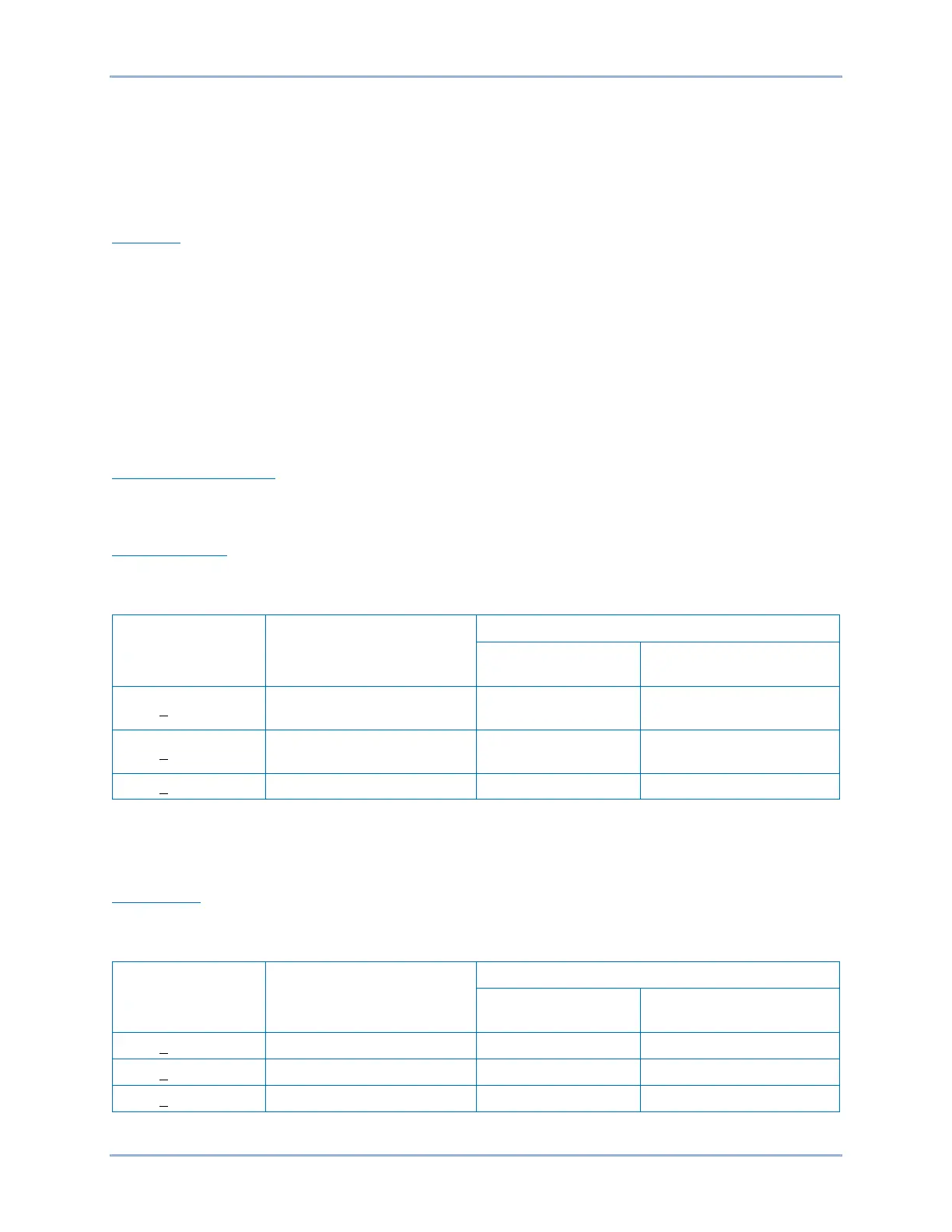
Contact-sensing turn-on voltages are listed in Table 249.
Table 249. Contact-Sensing Turn-On Voltages
Style Option Nominal Input Voltage
Contact-Sensing Turn-On Voltage*
Jumper Installed
(Low Position) †
Jumper Not Installed
(High Position) †
Gxx1xxxxxxxxxx 48 Vdc or 125 Vac/dc 26 to 38 Vdc
69 to 100 Vdc
56 to 97 Vac
Gxx2xxxxxxxxxx 125/250 Vac/dc
69 to 100 Vdc
56 to 97 Vac
138 to 200 Vdc
112 to 194 Vac
* AC voltage ranges are calculated using the default recognition time (4 ms) and debounce time (4 ms).
† Voltage ranges depend on jumper configurations. See the Contact Inputs and Outputs chapter for more
information.
Input Burden
Burden values shown in Table 250 assume nominal value of input voltage applied.
Table 250. Contact-Sensing Input Burden
Style Option Nominal Input Voltage
Jumper Installed
(Low Position)
Jumper Not Installed
(High Position)
Specifications BE1-11g
 Loading...


