620 9424200994 Rev N
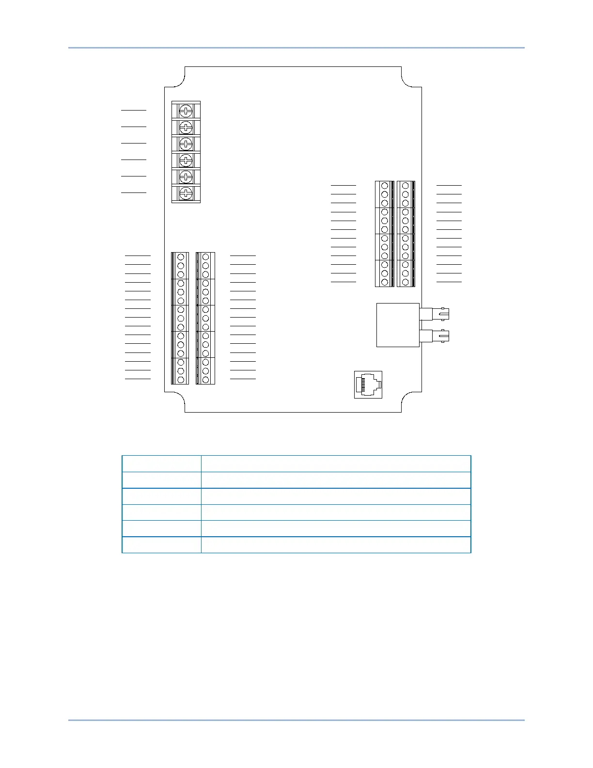
Figure 366. Input and Output Terminals
Table 256. Input and Output Terminals
Operating Power and Alarm Contacts
RTD Inputs 1, 3, 5, 7, 9, 11
RTD Inputs 2, 4, 6, 8, 10, 12
Analog Outputs 1 - 4 and RS485 Connection
External Analog Input Connections
Voltage input connections are shown in Figure 367 and current input connections are shown in Figure
368. When using the current input, AIN V+ and AIN I+ must be tied together.
7
8
9
10
11
12
13
14
15
16
17
18
19
20
21
22
23
24
25
26
27
28
29
30
31
32
33
34
35
36
48
47
46
45
44
43
42
41
40
39
38
37
60
59
58
57
56
55
54
53
52
51
50
49
RTD2+
RTD2-
COMM
RTD4-
RTD4+
RTD6+
RTD6-
COMM
RTD8-
RTD8+
RTD10+
RTD10-
COMM
RTD12-
RTD12+
RTD1+
RTD1-
COMM
RTD3-
RTD3+
RTD5+
RTD5-
COMM
RTD7-
RTD7+
RTD9+
RTD9-
COMM
RTD11-
RTD11+
RS485 C
RS485 B
RS485 A
NO CONN
AOUT4-
AOUT4+
AOUT3-
AOUT3+
AOUT2-
AOUT2+
AOUT1-
AOUT1+
AIN4I+
AIN4-
AIN4V+
AIN3I+
AIN3-
AIN3V+
AIN2I+
AIN2-
AIN2V+
AIN1I+
AIN1-
AIN1V+
P4 P3
J5 J4
1
2
3
4
5
6
PWR
PWR
GND
N.O.
COMM
N.C.
TB1
P0061-54
RTD Module BE1-11g