Terminals at the front of the ontroller b oard 6.13T
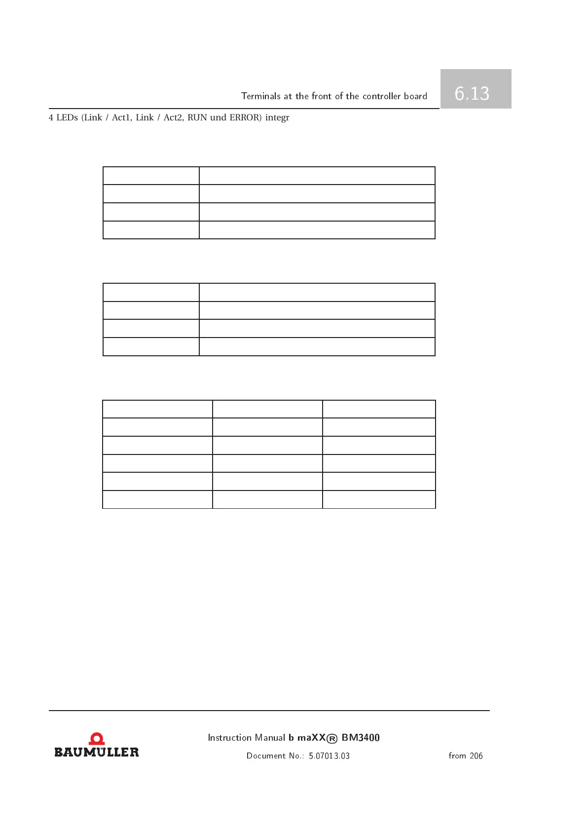
4 LEDs (Link / Act1, Link / Act2, RUN und ERROR) integrated into the connectors are used to display the
status of the EtherCAT module.
• Link / Act1 (green)
Display Meaning
Off No link at X1
On Link at X 1
Blinking Data transfer via X1 (Activity)
• Link / Act2 (green)
Display Meaning
Off No link at X2
On Link at X 2
Blinking Data transfer via X2 (Activity)
• RUN (green) / ERROR (red) Status of the state machine and error display
RUN-LED ERROR-LED Meaning
X On ERROR
Blinking On / Off Blinking Off / On INIT
200ms On / 1s Off Off PRE-OPERATIONAL
500ms On / 500ms Off Off SAVE-OPERATIONAL
On Off OPERATIONAL
Further error messages can be displayed using the service tool software.
For this the CAN terminating resitors in «Appendix B - Spare parts and accessories» on page 157 can be
used.
For cabeling within the switching cabinet the cables desribed under «Appendix B - Spare parts and acessories»
at page 159 can be used.
Instrution Manual
b maXX
®
BM3400
105
Doument No.: 5.07013.03 from 206
 Loading...