Controller terminals
Instruction handbook b maXX BM4400, BM4600, BM4700
Document No.: 5.12008.07 Baumüller Nürnberg GmbH
196
of 358
7.11
Standard
controller
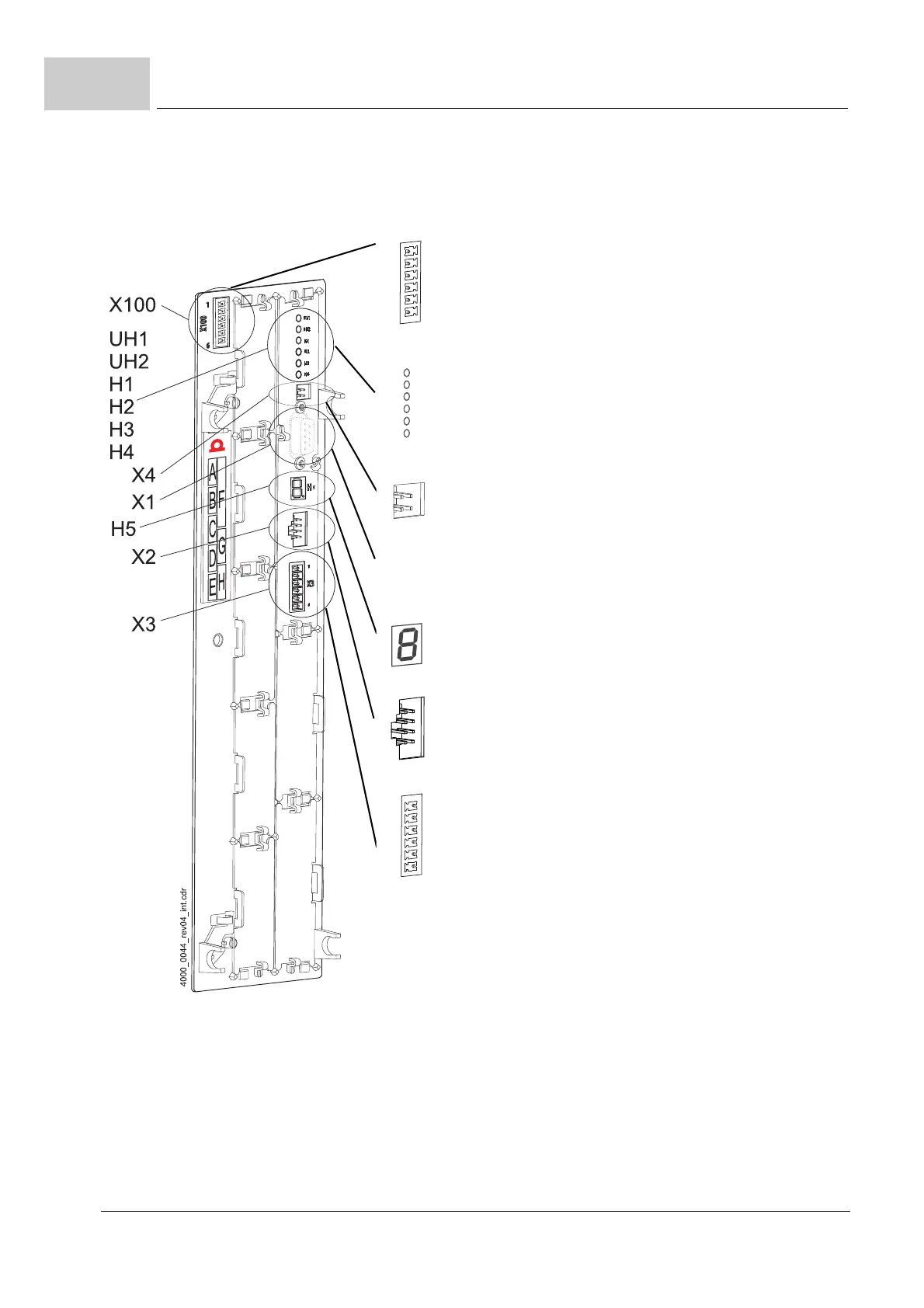
Figure 91: Connection X100 and terminals of a standard controller
X100-1: +24V (SELV/PELV)
1)
X100-2: +24V (SELV/PELV)
1)
X100-3: Power supply on (bus) (SELV/PELV)
2)
X100-4: Brake resistor on (SELV/PELV)
2)
X100-5: M24V (SELV/PELV)
1)
X100-6: M24V (SELV/PELV)
1)
UH1: reserved
UH2: reserved
H1: green: torque direction 1, yellow: torque direction 2
H2: green: enabling, yellow: Power ON
H3: red: current limit reached
H4: red: error
X4: reserved
X1, depends on controller type, see ZPage 198–
H5 7-segment display
4)
also see ZDisplay and operation elements– from page 132
X2:
Connection for Baumüller memory module PSI
3) 4)
X3-1: Ready for use ON (normally open contact) (SELV/PELV)
X3-2: Ready for use ON (change over) (SELV/PELV)
X3-3: Reference for 4 and 5 (SELV/PELV)
X3-4: Quick stop (SELV/PELV)
X3-5: Pulse enable (SELV/PELV)
X3-6: Ready for use ON (normally closed contact) (SELV/PELV)