Installation
Instruction handbook b maXX BM4400, BM4600, BM4700
Document No.: 5.12008.07
197
of 358
7
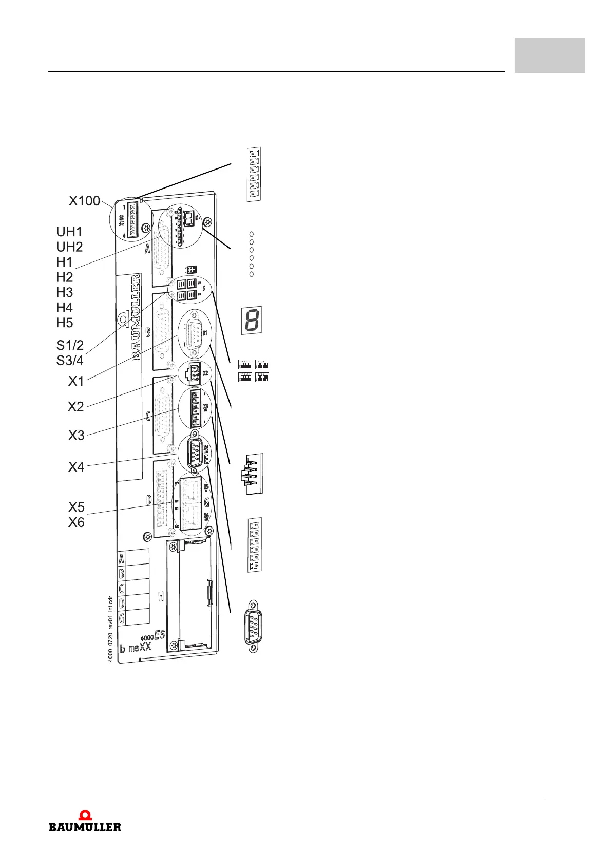
ES controller
X100-1: +24V (SELV/PELV)
1)
X100-2: +24V (SELV/PELV)
1)
X100-3: Power supply on (bus) (SELV/PELV)
2)
X100-4: Brake resistor on (SELV/PELV)
2)
X100-5: M24V (SELV/PELV)
1)
X100-6: M24V (SELV/PELV)
1)
UH1: reserved
UH2:
reserved
H1:
green: torque direction 1, yellow: torque direction 2
H2:
green: enabling, yellow: Power ON
H3:
red: current limit reached
H4:
red: error
H5 7-
segment display
4)
also see ZDisplay and operation elements– from page 132
S1/2 Address switch to set controller IP address
S3/4 Also see
ZAddress
switch S1 - S4 (only ES controller)– from page 136
X1, depends on controller type, see ZPage 198–
X2:
Connection for Baumüller memory module PSI
3) 4)
X3-1: Ready for use ON (normally open contact) (SELV/PELV)
X3-2: Ready for
use ON (change over) (SELV/PELV)
X3-3:
Reference for 4 and 5 (SELV/PELV)
X3-4: Quick stop (SEL
V/PELV)
X3-5: Pulse enable
(SELV/PELV)
X3-6:
Ready for use ON (normally closed contact) (SELV/PELV)
X4-1: Analog input 1 + (SELV/PELV)
X4-2: An
alog input 2 + (SELV/PELV)
X4-3: Refere
nce analog output 1 and 2 (SELV/PELV)
X4-4: Analo
g output 1 + (SELV/PELV)
X4-5: Analo
g output 2 + (SELV/PELV)
X4-6: Refere
nce analog input 1 (SELV/PELV)
X4-7: Refere
nce analog input 2 (SELV/PELV)
X4-8: Refere
nce analog output 1 and 2 (SELV/PELV)
X4-9: Refere
nce analog output 1 and 2 (SELV/PELV)
X5, X6 depends on controller type, see ZPag
e 200–