1 695 106 288 2013-10-30| Beissbarth GmbH
Product description | MS 63 | 25 en
3.6 Description of function
Below are reported the main functions of the listed
components of the MS 63:
R Pedal box, comprehends control pedals of the equi-
pment (locking flange rotation pedal, bead breaking
pedal, locking jaws pedal, tilting column pedal).
R Bead breaker, for the bead breaking of the tire from
the rim; it is composed of the bead breaking arm
pneumatically operated by a double effect cylinder,
the arm positioning lever, the antiabrasive supports
for supporting the rim during bead breaking phases.
R Column assembly, made of a tilting column which
holds the components needed to demount (and
mount) the tire from the rim: the horizontal sliding
arm (with the mounting lever), the vertical sliding
rod (with the locking knob), the mounting tool for
demounting (and mounting), with the help of the
bead lifting lever, the tire from the rim.
R Locking plate, made of the locking and rotation
device (clockwise and counter-clockwise) of the
rim, pneumatically driven by 2 cylinders, made of 4
movable lanes with locking jaws for the internal and
external locking of the rim.
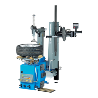
3.5 Description of unit
On the MS 63 there are rotating and moving
parts that could injure fingers and arms.
2
4
3
1
5
7
8
13
12
14
15
18
17
16
6
9
11
10
21
19
652013-01_Mi
Fig. 1: MS 63
Pos. Name Function
1 Locking flange rotation pedal Locking plate rotation:
R clockwise (press down the pedal)
R counter-clockwise (lift the pedal from bottom to top)
2 Bead breaker pedal Bead breaking arm activation.
3 Locking jaw pedal Opening and closing of the locking plate jaws.
4 Tilting column pedal Tilting column activation.
5 Bead breaking arm Bead breaking of the tire from the rim.
6 Bead breaking arm lever Bead breaking arm activation.
7 Bead breaker blade Bead breaking.
8 Antiabrasive supports Tire support for bead breaking operations.
9 Tilting column Sliding arm and mounting tool support .
10 Horizontal sliding arm Horizontal positioning of the mounting tool.
11 Locking lever Tire locking of the horizontal sliding arm.
12 Vertical sliding rod Vertical positioning of the mounting tool.
13 Vertical rod locking lever Tire locking of the vertically sliding rod. Operating on the knob it is possible to achieve a 3 mm
spacing (adjustable) from the edge of the rim.
14 Mounting tool Mounting and demounting of the tire from the rim (with the help of the bead lifting lever).
15 Sliding roller To be inserted in the mounting tool BOX, to avoid any kind of friction between the rim and the
mounting tool during tire mounting and demounting phases. For the alloy rims a special "tab"
is arranged.
16 Locking plate Locking and rotation of the rim.
17 Movable lanes Positioning of the locking jaws.
18 Locking jaws Internal or external locking of the rim.
19 Grease cup holding ring Mounting paste containing support.
20 Bead lifting lever Lifting of the tire edge in demounting and mounting phases.
21 Speed switch Passing from the first to the second speed.
 Loading...