1 695 106 288 2013-10-30| Beissbarth GmbH
28 | MS 63 | Initial commissioningen
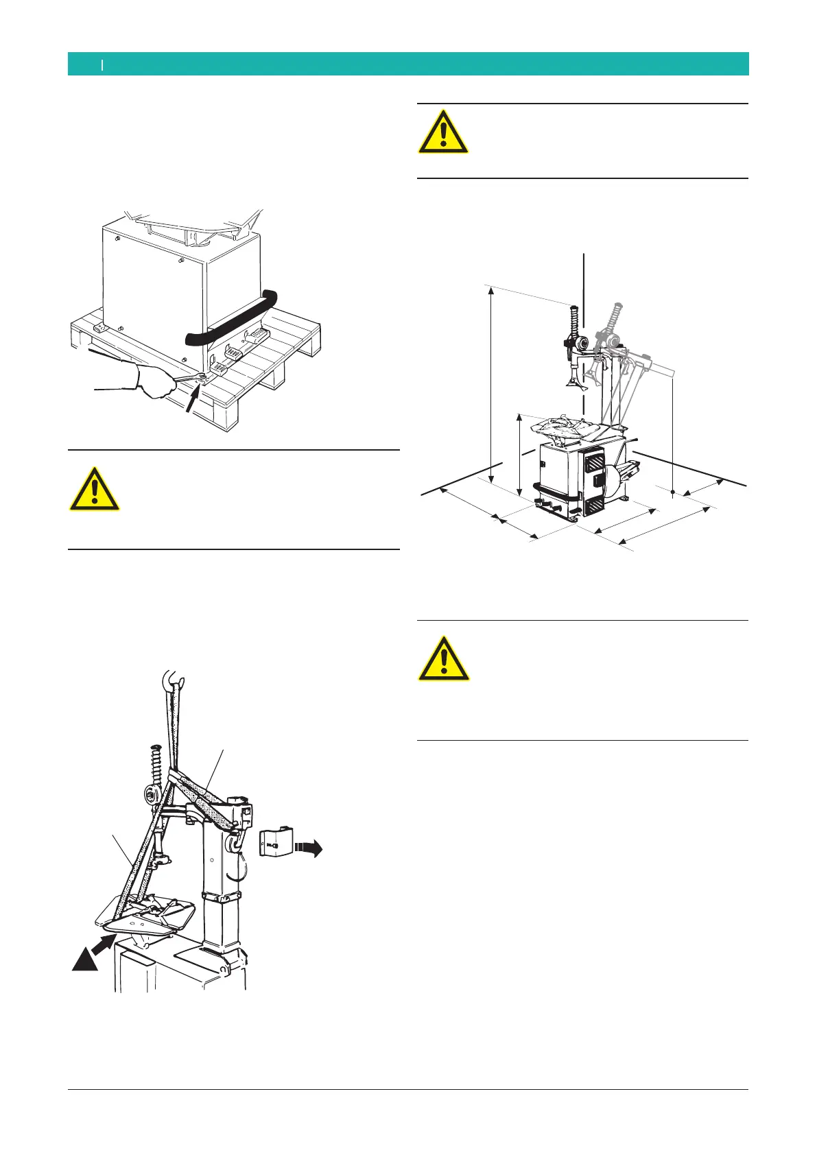
4.2.6 Machine positioning
1. Put back in place the side door.
2. Loosen the two screws that fix MS 63 to the pallet.
652012-12_Mi
Warning - damage risk!
The lifting belts can crush the flexible supply
pipes of the cylinder or damage the applied
parts of the MS 63.
¶ Insert the lifting belts carefully.
3. Remove the back protection of the locking lever, as
shown.
4. Insert the appropriate lifting belts (length belt 1: 1
Mt, belt 2: 3 Mt), with sufficient capacity, as shown.
652013-02_Mi
2
1
!
Warning - tilting danger!
The barycentre of the MS 63 does not lie in
its centre.
¶ It is necessary to lift the machine slowly.
5. Lift the MS 63 with a lift crane and install it in the
designed area respecting the minimum distances as
shown in the picture.
652013-03_Mi
500
760
1830
760
950
1530
500
For safe and ergonomic use of the MS 63 it is recom-
mended to leave a minimum of 500 mm space from the
surrounding walls.
Warning - tilting danger!
During tire inflation considerable forces are
exerted.
¶ The MS 63 has to be fixed in at least 3
points on the floor (screw holes see chap.
4.2)..
i In each screw hole are placed shock absorbers, to
allow a vibration free installation .
6. Put an appropriate lubricator in the mounting paste
holding device.
 Loading...