1 695 106 288 2013-10-30| Beissbarth GmbH
Initial commissioning | MS 63 | 29 en
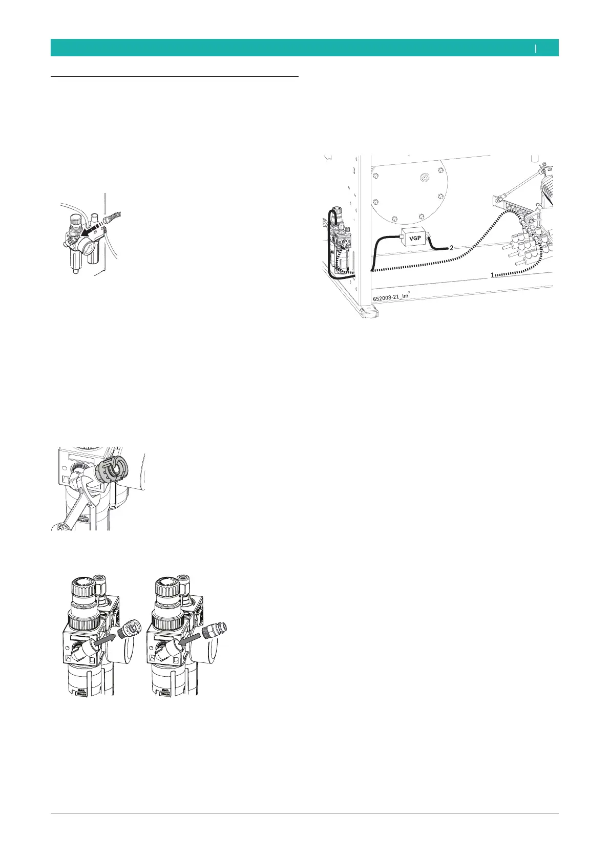
4.3 Pneumatic connection
1. Connect the MS 63 to the compressed air supply
unit.
2. In case a bayonet connection is used, approach the
air pipe to the filter unit connection and tighten the
threaded collar.
3. Adjust to a pressure between 8 and 12 bar.
Pull the red knurled screw (pressure reducing val-
ve) first upwards and then twist it to adjust ope-
rating pressure.
Check pressure on the manometer.
! A 1/4 threaded quick connection is supplied to allow
the pneumatic connection when the operator is not
provided with a bayonet connection.
4. Using a 14 spanner, loosen the rotating joint on the
filter unit.
5. Remove the rotating joint and place the quick con-
nection; finally tighten using the 14 spanner.
! To calibrate the lubricating oil flow, refer to the
Maintenance chapter.
6. Connect the air tubes coming from the filter as
shown in the figure below.
7. Connect the feed tube of the pneumatic blocking on
the only free joint of the pedal (1).
i The outlet 2 of the VGP valve inside the casing sup-
plies the inflation system.
8. Connect the inflation gun, with built-in pressure
gauge, to the VGP valve.
! The manometer placed at the eyes height supervises
the tire inflation.
! The manometer is in compliance with directive
87/217/EEC. The button placed on the manometer
side is used to drawn air from the tire.
 Loading...