Chapter 3 Functional Safety
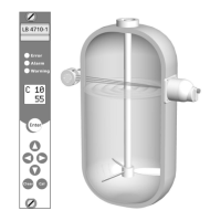
Mini-Switch LB 471
3.2 Safety Function
The safety function of the measuring system comprises the detec-
tion and indication of changes in the count rate of the detectors
caused by the presence of product being measured in the measur-
ing path between radiation source and measuring system.
The safe status is dependent on the mode of operation:
Maximum level (overflow protection): Product between radia-
tion source and detector -> low count rate
Minimum level (protection against running dry): No product
between radiation source and detector -> high count rate
3.3 Safety Requirement
Operating mode with
low demand rate
Operating mode with high
or continuous demand rate
3.4 Project Planning
Please make sure that the measuring system will be used in
accordance with its designated function.
The application-specific limits have to be observed and the
specifications must not be exceeded. See also the technical da-
ta and ambient conditions in the User’s Manual.
The fault tolerance time of the overall system must be greater
than the reaction time of the measuring system.
The relay contacts have to be protected by a 1A fuse.
The digital inputs 1 and 2 must not be closed in case of a safe-
ty-related application.
General instructions and
restrictions