Chapter 5 Installation
Mini-Switch LB 471
5.2.4 Installation of the GM Detector
Collimator
Connection room
Screwed cable gland
The lateral opening (radiation window) in the collimator covers the
sensitive area of the detector; it has to face the source.
If the bracket cannot be installed on the container, then it has to
be mounted on the girder located in the vicinity. Figure 15 shows
three alternative proposals for installing the detector (A, B, C).
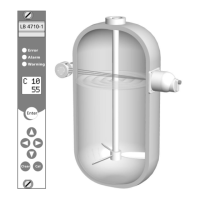
Figure 14:
NaI detector mounted on a
container
Figure 15:
Alternative installations
Bracket
provided by
customer