Chapter 8 Electrical Installation
Mini-Switch LB 471
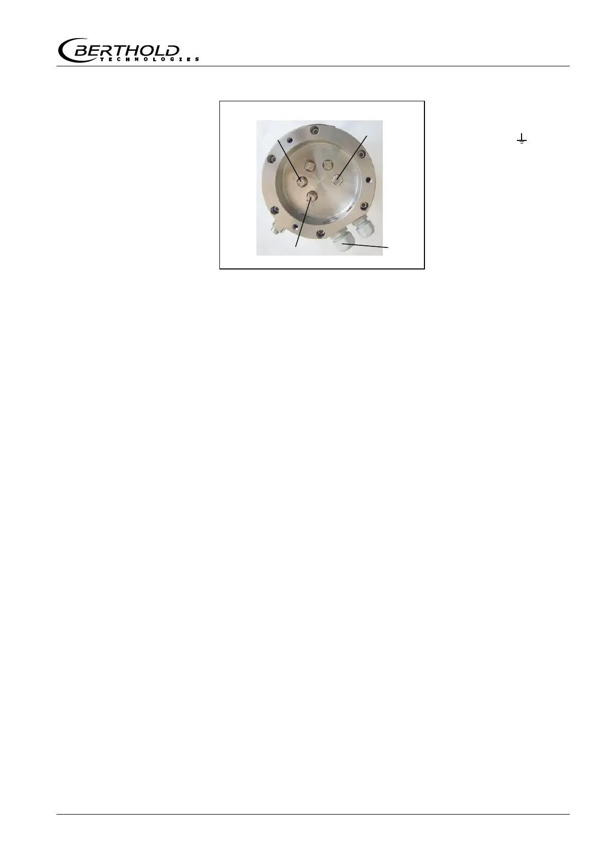
Terminal 2 (-)
Terminal 5 ( )
Cable bushing M16
7
Attach cover again and fix it
8
Connect grounding on the outside of the grounding screw at
the detector.
9
Place wires on evaluation unit. See connection diagram on
page 137.
8.1.3 Installing the GM Detector
1
Install cable between evaluation unit and detector. For maxi-
mum cable length see the technical data on page 105.
2
Unscrew three screws at the detector cover.
3
Take off cover.
4
Insert line.
Cable bushing (PG 16) for cable Ø 6 to 8 mm. Cable bushing
has to face down in order to prevent water from penetrating.
Figure 37:
Terminal assignment
NaI detector