Chapter 5 Installation
Mini-Switch LB 471
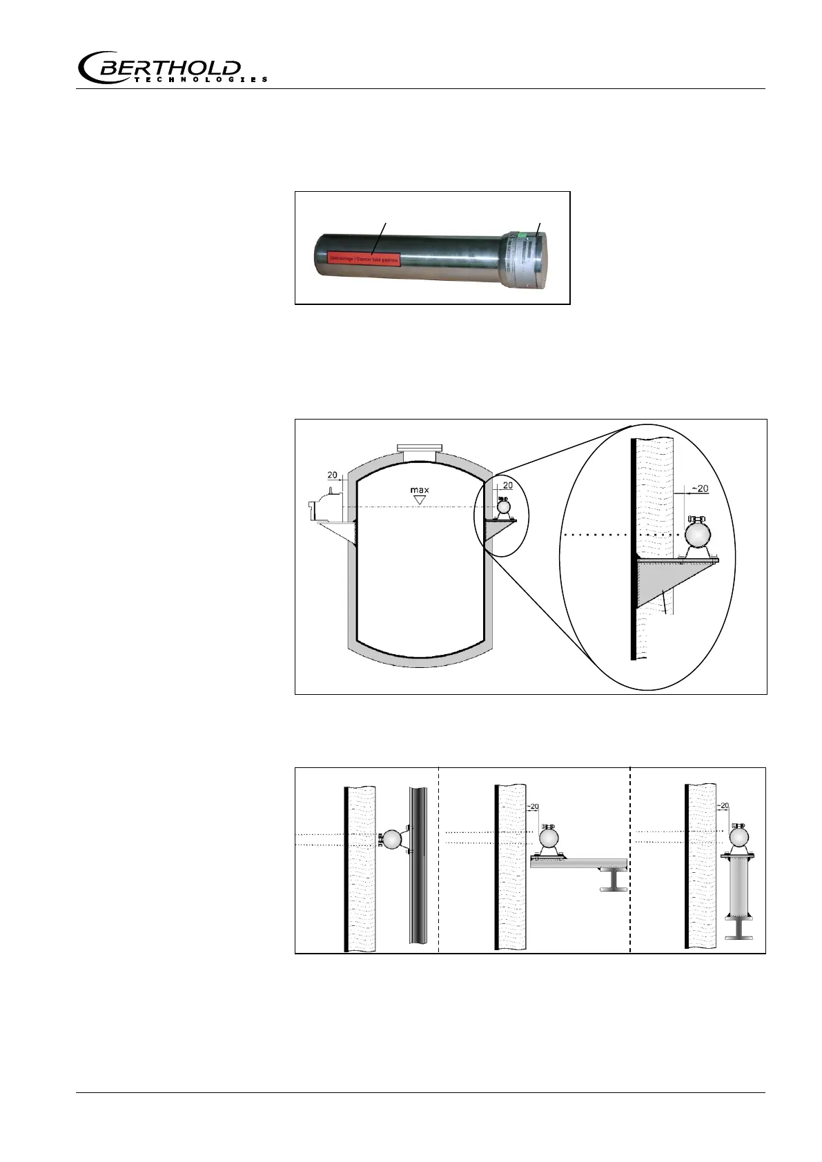
5.2.3 Installation of the GM Detector
Red marking strip for
counter tube position
Align the detector horizontally exactly on the level of the source.
The red marking strip on the case shows the position of the coun-
ter tube in the detector. The counter tube must not be covered by
the holder or by clamps, as this would adversely affect the sensi-
tivity of the measurement.
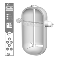
If the bracket cannot be installed on the container, then it has to
be mounted on the girder located in the vicinity. Figure 10 shows
three alternative proposals for installing the detector (A, B, C).
Figure 9:
Installation on container
GM detector
Figure 10:
Alternative installations
Bracket
provided by
customer