Chapter 5 Installation
Mini-Switch LB 471
5.2 Installing the Detector
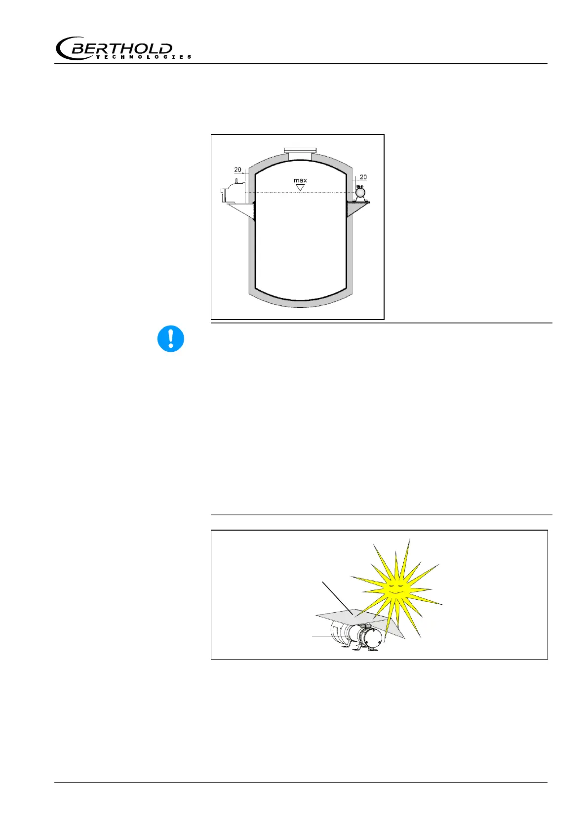
Mark the level to be moni-
tored at the container. Posi-
tion the detector there in a
horizontal line with the
source. At the same time, the
horizontal line is the limit lev-
el where the device is switch-
ing. Make sure that the radia-
tion window of the detector is
not covered by the holder.
The distance to the surface of
the container or the heat in-
sulation should be approx 20
mm.
The detector may be damaged by heavy mechanical strain, vibra-
tions and high temperatures.
The detector has to be mounted free from vibrations. During in-
stallation and operation, the detector must not be exposed to me-
chanical strain.
The ambient temperature must not exceed the values stated in
the technical data section (see chapter 13.2). If the ambient tem-
perature is higher, the detector has to be cooled. Appropriate wa-
ter cooling jackets are available as extras. See also Chapter 6
Water Cooling and the technical drawings on pages 121 to 130.
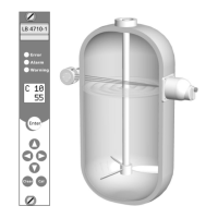
Direct exposure to sunlight is not permitted as this may lead to an
unacceptable increase of the surface temperature. In these cases,
you have to install a canopy top (see Figure 6).
Figure 6:
Detector with canopy top