Chapter 7 Shielding Installation
Mini-Switch LB 471
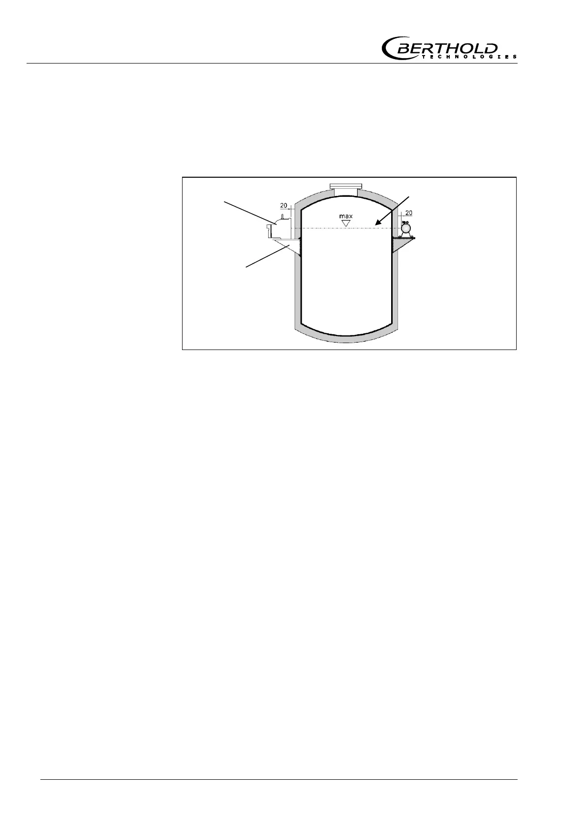
Source and center of the detector have to be installed on a hori-
zontal line. At the same time, this horizontal line is the monitoring
level where the device switches.
The shielding is installed at the measuring point by means of
brackets.
1
Install suitable bracket which has to be provided by the cus-
tomer on the respective level. See installation proposal below.
2
Unpack source with shielding and mount it on the respective
bracket.
If you are working with a shielding with pneumatic shutter, a com-
pressed air connection has to be available. Signals supplied by an
optional limit switch have to be connected via an electrical line
(see Shielding LB 744X with Pneumatic on page 132).
7.2 Installation Proposal for Shielding
The shielding container comprises a lead-filled sturdy cast iron
case. A revolving shutter is installed to close the radiation exit
channel. This shutter is operated from the rear side via a lever,
which can be locked by means of a padlock in its open or closed
position.
For installation, the shielding container includes a cast-on flange
and in addition a fastening foot with threaded holes.
The specifications for the required drilled holes are listed in the
Appendix on page 131.
Figure 33:
Installation on
a container
Bracket provided
by customer