35
6 - Motore Release 01 Date 09/2007
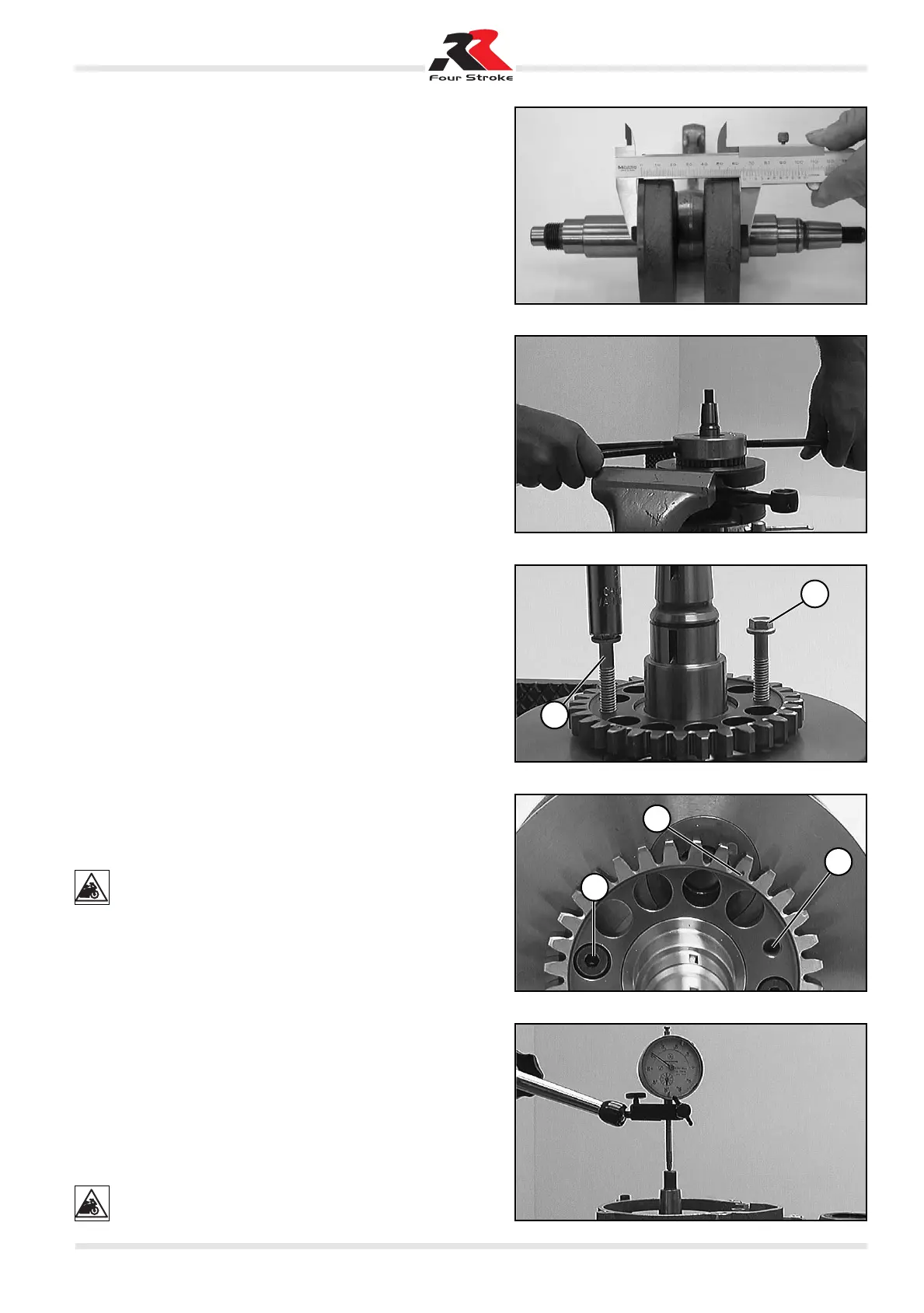
Measuring the outside diameter of the handwheels
Using a vernier caliper, measure the outside diameter of the
handwheels as shown in the figure.
Outside diameter of handwheels = 65 mm ± 0.05 mm
Countershaft gear
– To remove the countershaft gear from the crankshaft, it is first
necessary to remove the inner ring nut of the cylindrical roller
bearing (see below).
– Whenever the cylindrical roller bearings are replaced, the in-
ner collars on the crankshaft also need to be replaced.
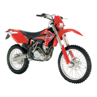
– To this end, clamp the crankshaft in a vice by the shaft section
fitting the inner collar to be replaced.
– Heat special tool Part No. 3625193 on an electric hotplate to
approximately 150° C and immediately push it onto the inner
collar. Squeeze the special tool hard to obtain good heat tran-
smission and remove the inner collar from the crankshaft.
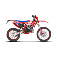
– Remove the two screws from the countershaft gear.
– Insert the two screws 1 into M6 threaded holes 2.
– Remove the countershaft gear from the crankshaft and evenly
tighten the two screws.
– Before fitting the countershaft gear, heat it to approximately
100° C.
– Degrease the two countershaft gear fixing screws and apply
Loctite 243 to their threads.
– Fit the countershaft gear to the crankshaft so that mark C is in
the coupling shaft area.
– Fit the fixing screws and tighten to 8 N·m.
– Before fitting a new inner collar, heat the special tool again to
about 150° C, fit it with the inner collar and immediately push
it onto the shaft section.
– Allow the inner collar to cool down for about 30 seconds and
then, using a suitable tube, hit the inner collar until it is seated
properly.
– After replacing the inner collars, measure the crankshaft axial
play.
NEVER ATTEMPT TO INSERT AN INNER COLLAR BY
HITTING IT WHILE THE CRANKSHAFT IS HELD IN A VI-
CE BY A SHAFT SECTION. THIS WOULD RISK COM-
PRESSING THE SHAFT SECTIONS, MAKING THE CRANK-
SHAFT UNUSABLE.
Compensating for the crankshaft axial play
– Insert the crankshaft in the right-hand crankcase half and fit
the crankcase gasket.
– Fit the crankcase screws in the engine base area and tighten them.
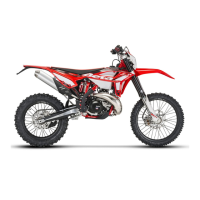
– Fit the comparator on the crankcase and measure the crank-
shaft axial play.
Axial play: 0.1 - 0.2 mm
– If the measurement does not correspond to the nominal value,
proceed to rectify the axial play.
– To this end, remove the crankshaft and then remove the inner
collar from the crankshaft on the ignition side using the spe-
cially designed tool. Then add or remove thrust washers as
necessary.
Add thrust washers if the axial play is excessive and re-
move them if the axial play is too small. Thrust washers
can only be added on the ignition side.
1
1
C
2
2