17
6 - Engine Release 01 Date 09/2007
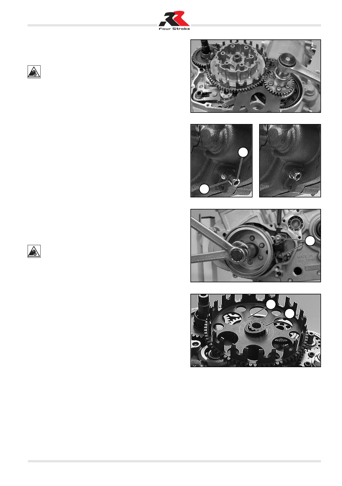
– Position the special tool as shown in the figure, unscrew the
primary torque gear flange nut and remove it.
– Remove the special tool.
THERE ARE FLANGE NUTS WITH LEFT-HAND AND
RIGHT-HAND THREADS. THE FLANGE NUTS BEAR-
ING THE CAPTION “LEFT” HAVE A LEFT-HAND
THREAD. THOSE WITH NO INSCRIPTION HAVE A RIGHT-
HAND THREAD.
– Bring the crankshaft to the top dead centre.
– Unscrew crankshaft fixing screw 1 and remove retaining ring
2.
– Manually screw in the crankshaft fixing screw.
– When resistance is felt, slightly move the flywheel to and fro
until the crankshaft screw is inserted in the related opening in
the crankshaft.
– Tighten the crankshaft fixing screw to 10 N·m.
Pulling out the flywheel
– Unscrew the two screws 3 and remove the pick-up from the
crankcase.
– Fit the puller and pull out the flywheel using the protective cap.
– Remove the key from the crankshaft.
NEVER HIT THE FLYWHEEL WITH A HAMMER OR AN-
OTHER TOOL AS THIS COULD CAUSE THE FLY-
WHEEL MAGNETS TO COME OFF AND DAMAGE THE
CRANKSHAFT. PUSH WITH THE PULLER TO AVOID BEND-
ING THE FIXING SCREW (250 CC MODELS).
Removing the clutch hub and drum
– Fit the protective cap to the driving shaft and then fit the puller.
– Remove the hub from the driving shaft.
– Remove from the driving shaft clutch drum 4 with the support
bush and the two thrust washers.
1
2
3
5
4