Access Easy Controller 18VAC Input Power Supply Card | en 125
Bosch Security Systems Hardware Manual Ver 2.0.0 | 2006.07
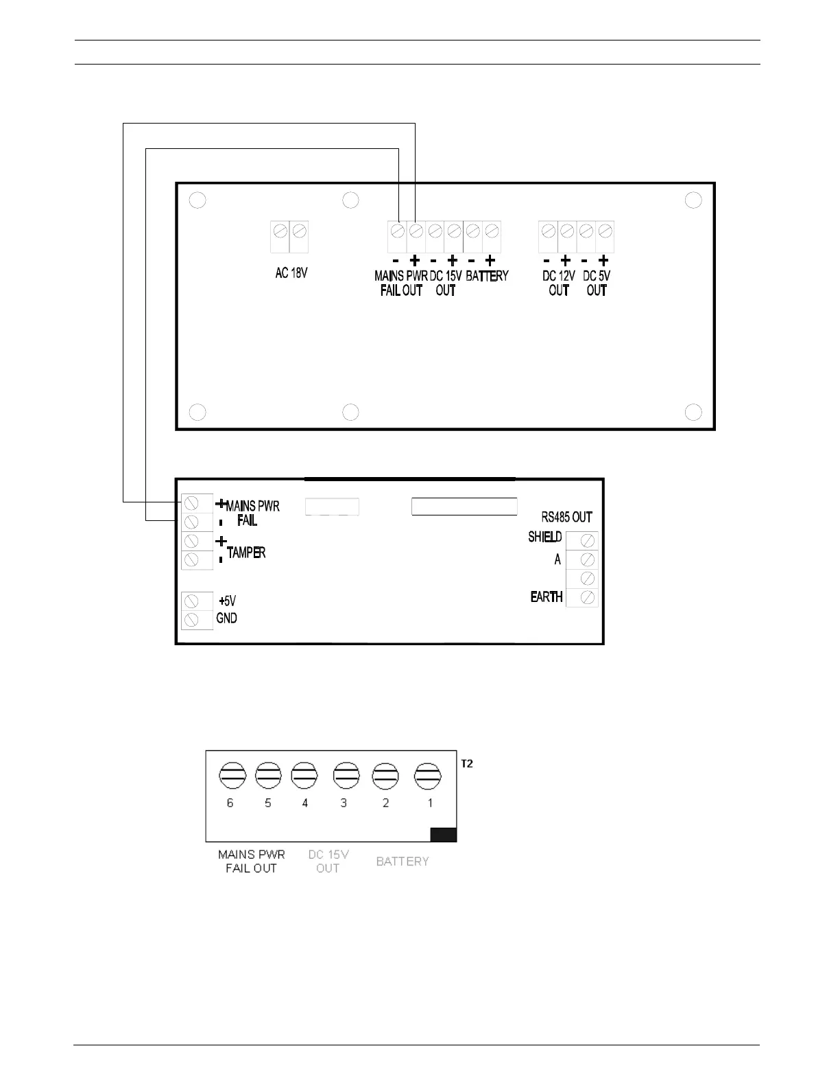
Internal wiring diagram between Power Supply board (UL Listed System) and Secure Com
Card
DC 15V Output (T2-4 & T2-3)
This output provides the power point for the rest of the cards in the same enclosure. Those
cards that required the 15VDC are Reader Board, I/O Cards and the Convertor Card, although
it is not a must to tap the power form this output, it serve as a termination point to loop the
power point to the rest of the cards that requires the 15VDC as shown in the following page.
CN2
CN1
B
P
I
N
1
P
I
N
1
(P/N: AEC MOD COM)
SECURE COMM. CARD
4
3
2
1
1
2
3
4
2
1
IN
T1
T2
(P/N: AEC MOD UPS2)
18VAC INPUT POWER SUPPLY BOARD
T3
5643 432121 21